Marmon Herrington Mk4 Armoured Car
For the latest update on progress, click here.
There two more updates on the blog
1 Aug 2016
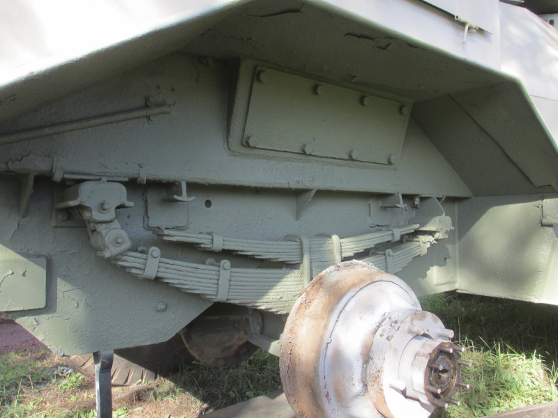
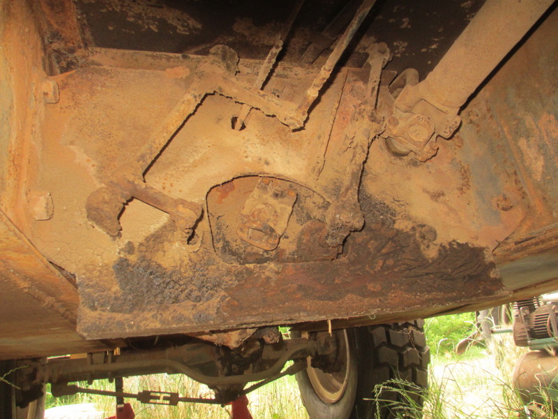
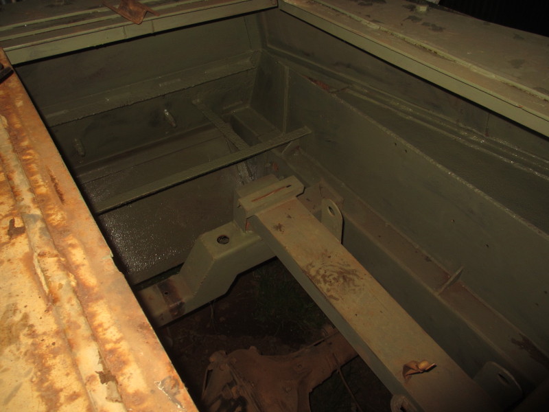
The job I had not been looking forward to, is done! Armed with goggles, a lamp and a cup-brush on a small angle grinder, I climbed in underneath the Car and removed as much of the rust as I could reach.
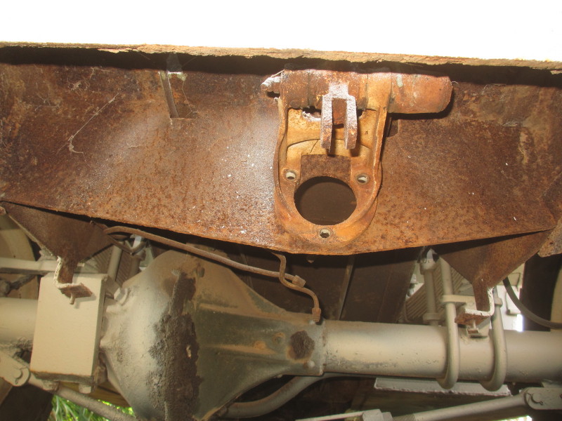
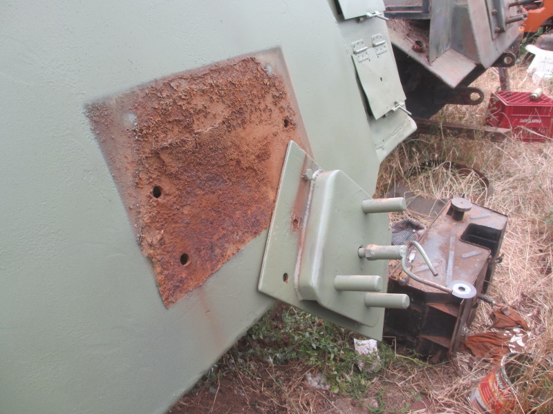
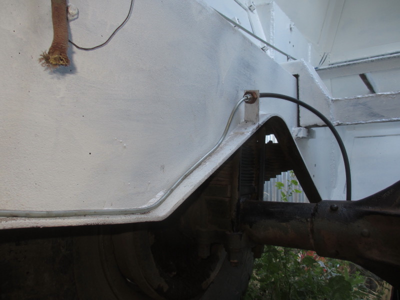
I was covered in the rust by the end, in my eyes, mouth, ears, hair, but it was worthwhile! I applied a liberal coat of Plascon UC501 primer not only under the driver's compartment, but also further back, under the fighting compartment and under the side tool-boxes. Soon it was looking a lot better!
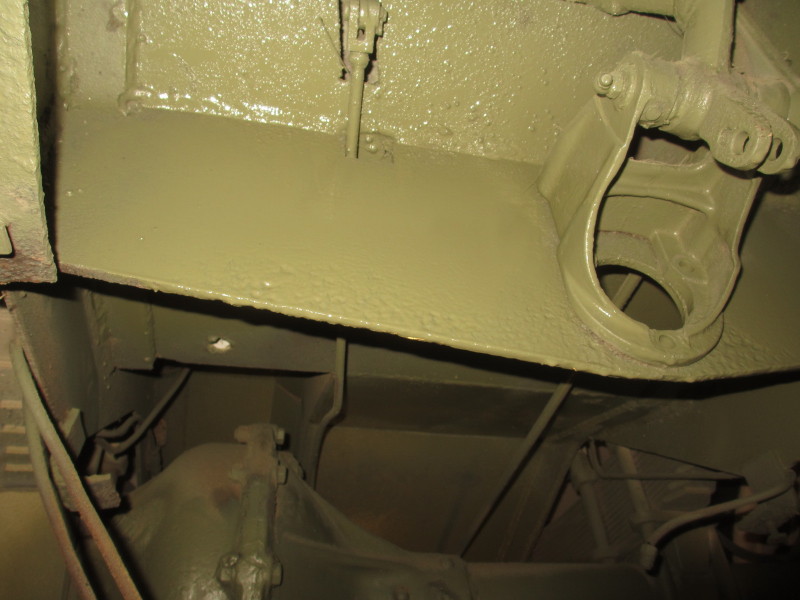
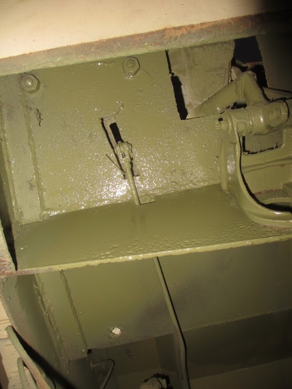
Those surfaces will probably get a coat of white, as with the engine compartment. The bracket for the Brake Master Cylinder can be seen, all ready for the re-sleeved and overhauled unit. The new brake pipes to join them up to the reconditioned rear brakes have also already been made. The front brakes must still be overhauled and new pipes made.
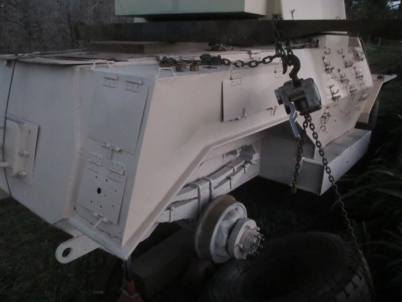
There was a job to do at the end of last week's report: the concrete-filled wheel on the right rear of the Car which will be a static exhibit, had to be refitted and it was too heavy to raise up into position. A stout wooden beam, a couple of chains and a chain-block were pressed into service. The wheel was soon back on!
A worrying issue is the amount of play in the steering on the Car which will be the runner; more than a quarter of a turn of the wheel before any resistance is felt. I felt the steering in the other Car, almost no play! Also the steering wheel itself on that Car is in much better condition. I distinctly remember my late father mentioning they had problems (on the earlier Marmon Herrington Cars) with what they called the 'Sector Shaft' on the steering.
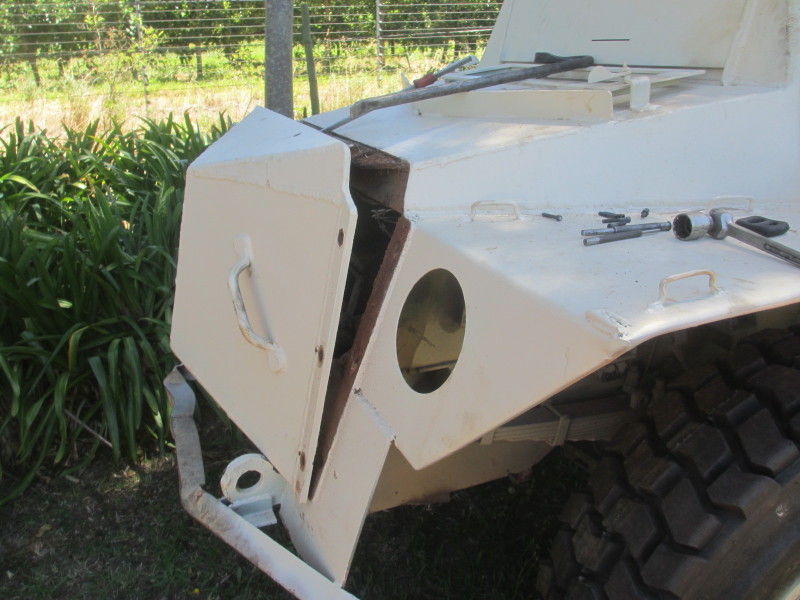
The simplest solution then is to swop the whole steering boxes over, complete with their columns and steering wheels. The spacer tube with two flanges will have to be removed first on both Cars. I removed the nose cone from the other Car, which was just loosely fitted. One bolt is out so far out of the 16 altogether and it didn't give up easily!

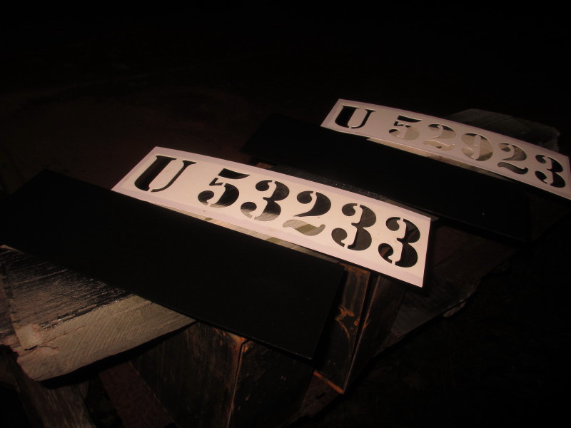
I tried out the stencils again on the flat steel plates I'd primed and painted last week. This is probably as smart as they will ever be:
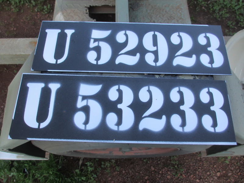
These are for the back of both Cars, at the front they'll be applied direct on to the nose cones.
The only other job I managed to get done was to remove the twisted centre section of the front 'bumper'. I plan to make a new bumper for the full length and fix it to the front of the remaining outer sections.

Nothing else to report, mainly because we have a Show next weekend for the West Cape Veteran Tractor & Engine Club at Moreson outside Malmesbury, north of Cape Town, and I needed to prepare an engine. One of the themes of the Show is JI Case. I'm a Stationary Engine collector and I was lucky to be given a Case DE engine many years ago. It probably ran last at a show in Paarl ten years ago, and it needed a lot of work to coax it back into life, then load it on to my Austin FG lorry which will be another exhibit.
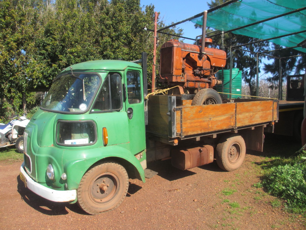
It can be seen running for the first time on this short clip: https://youtu.be/G20dTjUcxEo
25 July 2016
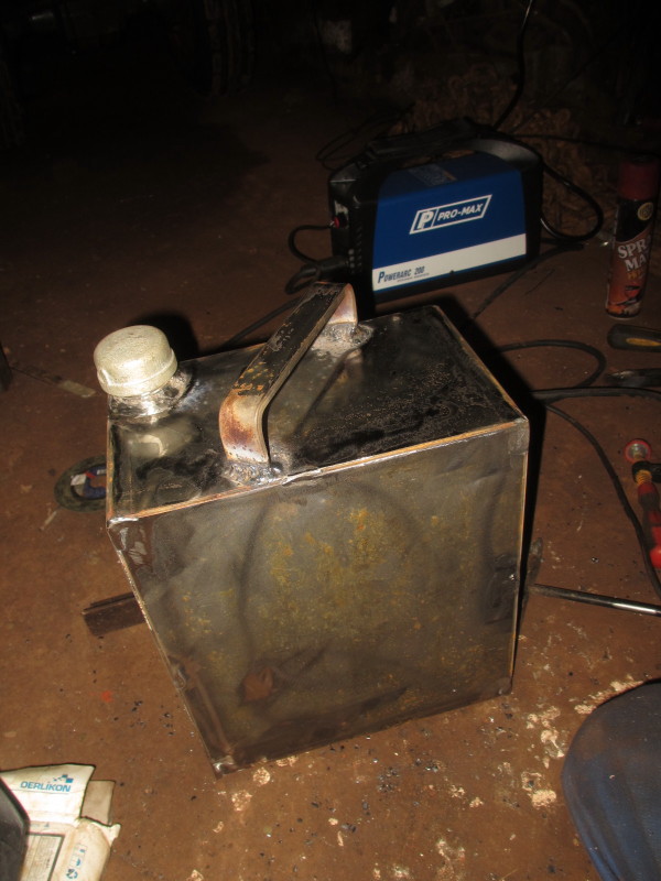
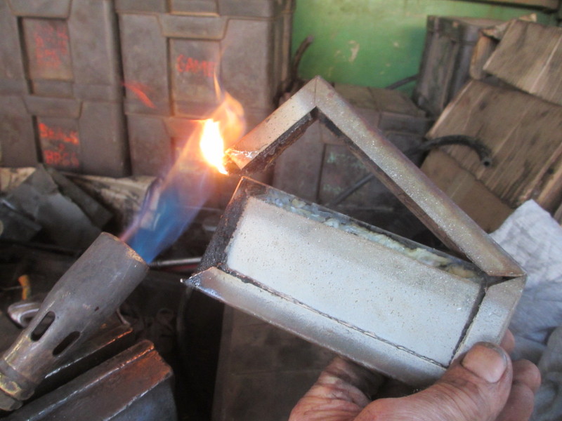
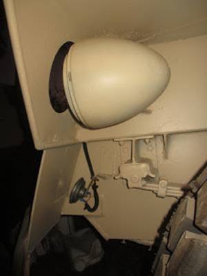
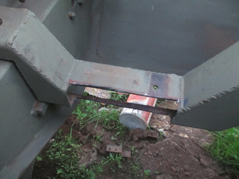
An early finish from work on Friday gave me the opportunity to weld up the first dummy fuel-can. The two bent-up channels which fit exactly into one another are now just tacked at the corners and half-way up and the filler neck is just welded on top for show. These cans, if you can find them, are two-gallon capacity and should have a brass screw cap. I have heard that in hot conditions, the lighter fractions of the fuel would evaporate through a breather hole in the cap and it was difficult to make an engine run properly on the remaining fuel. Here is an example of a commercial one:

This is what the first dummy can looked like:
Primed, painted and in its place, one down, two to go!
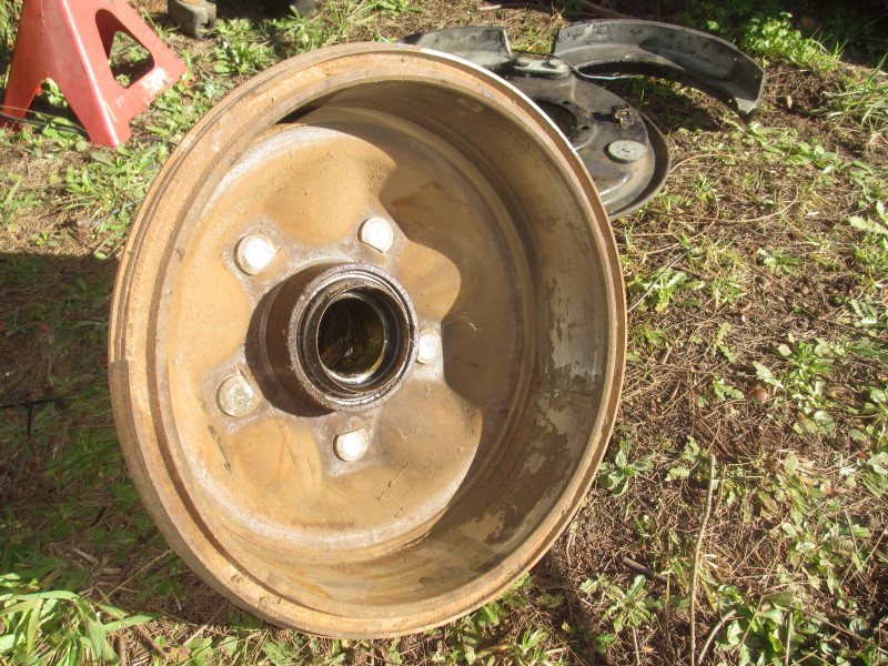
As I was hoping, the right rear brakes on the other Car which will be used as a static exhibit were in good condition, dry and with plenty of lining on the shoes.
Likewise the drum was hardly worn. This hub has the correct right-hand-thread studs for the right hand side of the vehicle.
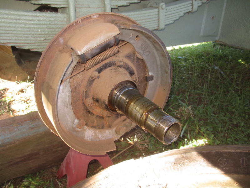
So I took off the whole back-plate from the 'static' Car and removed the slave cylinder and cleaned up the metal and primed and painted it. But first I ground out a groove for any oil which might leak past the seal and be caught in the cone, to leak out on the back-plate, rather than on to the brake linings.

A spare slave cylinder had been re-sleeved and overhauled so I fitted that and fitted the assembly to the axle of the 'runner'.

The cone for catching any leaking oil can be seen refitted here. I applied a light coating of gasket sealer to the joint face.
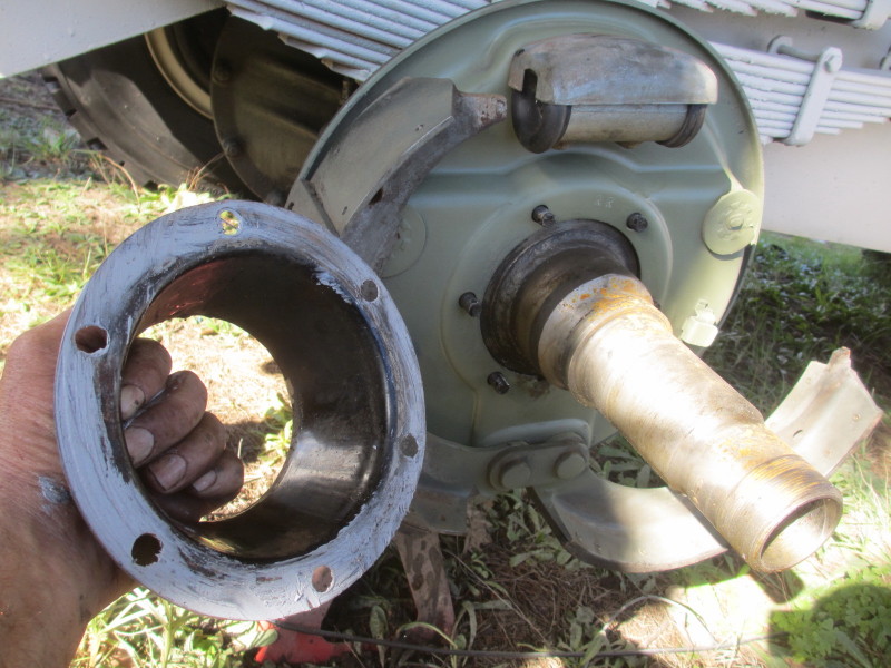
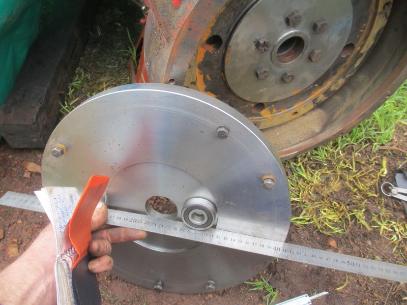
Another job which was done a long time ago was the seal housing was machined for a 'modern' seal. The originals were leather. So this needed to be fitted in place of the old one in the hub.

So that drum is now on, the brake shoes adjusted, all ready to bend up the new brake pipes which were also made up several months ago.
More priming and painting was mostly inside the right rear wheel arches of both Cars, while the wheels are off. I can't lift the concrete filled wheel back into position on my own, it's simply too heavy!
In the week, two steel plates were guillotined for the rear number plates. While other things were being painted, these got a coat of primer on both sides and a coat of black to one. The black paint was still too tacky this evening to experiment with the stencils!
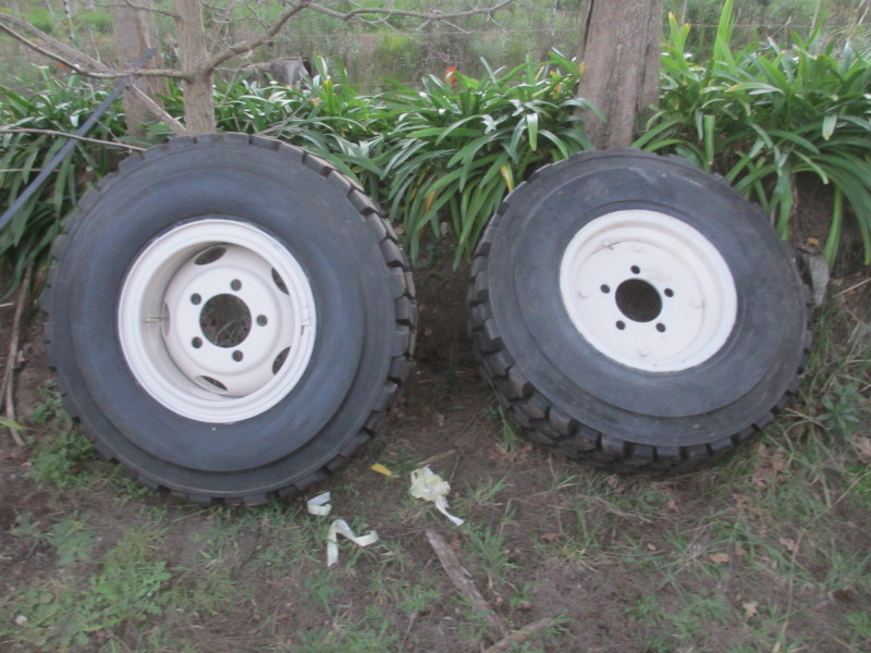
In the week also the fifth new tyre was fitted to the spare rim we've made up.
The next job which will be far from pleasant will be cleaning up under the vehicle below the driver's position and refitting the Brake Master Cylinder. That was also re-sleeved and overhauled a long time ago. The rear brakes can then be connected and tested. The master cylinder top-up cap is right down at the driver's feet. This is a good reason why I haven't refitted the nose plate.

All is on course for the launch of the restored Car as well as the static exhibit which will probably be mounted on a flat-wagon, part of the Military consist, at the Stars of Sandstone event at the end of March next year.
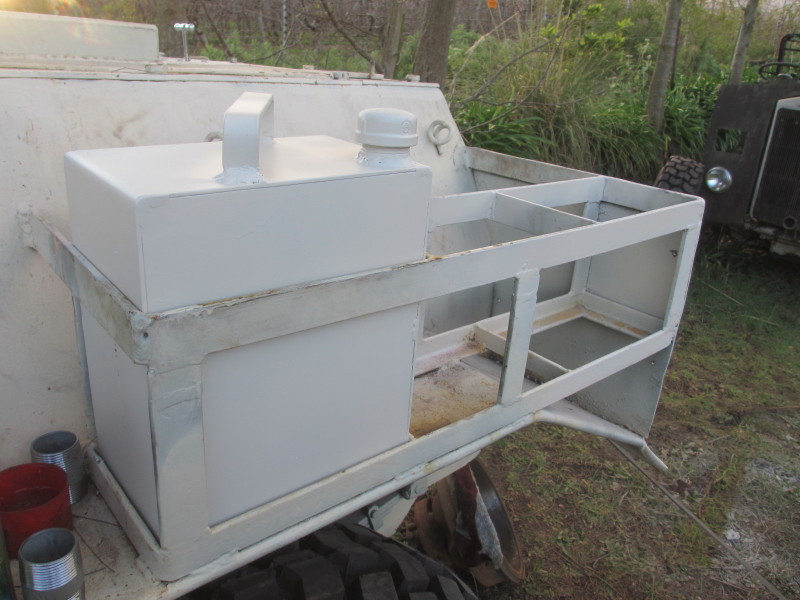
Fuel Tank Fits!
26 June 2016
The tank needed a little bit of attention at the Radiator Repairers, soldering the little leaks I expected in the welds. I asked that it not be painted there as I wanted to prime and paint it properly. At the same time it seemed a good opportunity to prime the top hatch covers.
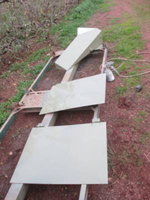
The Marmon Herrington Mk4 did not have covers in service. These will be fitted for security and it will be possible to remove them for authentic photos. The tank had to be black, the covers Desert Sand. The 'spray booth' leaves a lot to be desired!

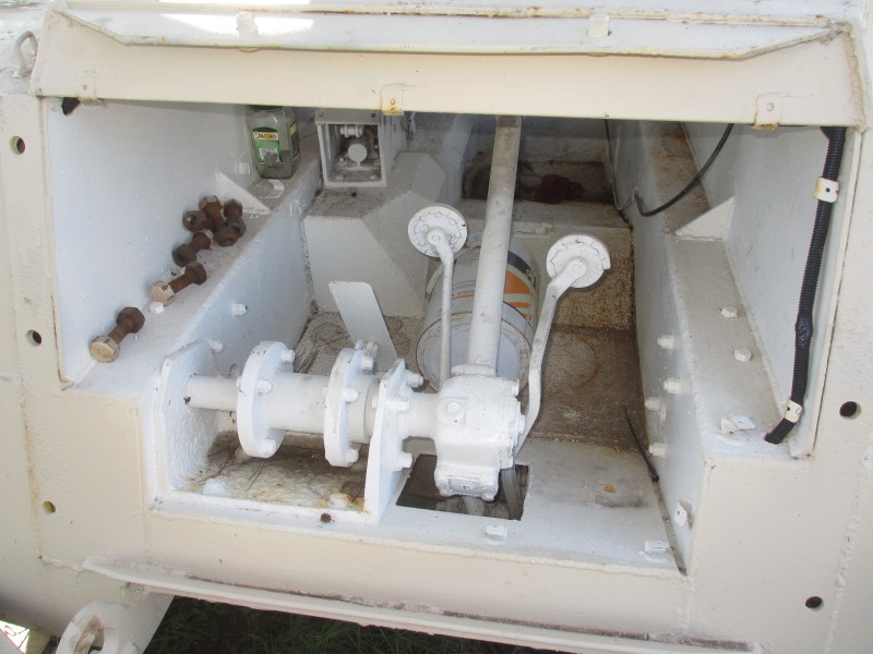
From memory, the engine compartments were completely empty when I removed the tanks (hoping that at least one would be serviceable). With the engine, radiator, pipes and fan shaft in position, fitting the new tank wasn't going to be easy! It was obvious that at least some of the engine top cover plates would have to come off. I wasn't sorry, because there were signs of rust from the join between the sides and the top.

Would all the bolts come out? One or two broke off and will have to be drilled out, but the sticky ones were the countersunk screws! There were two types, one with a screwdriver slot (which weren't likely to come loose after all these years!) and an old type of plough-bolt with one notch, not the square shoulder which is popular these days. There was nothing for it but to drill them out!
It was necessary to drill about eight of them, luckily the steel was 'soft'. First it was the side cover, then the back one. As the joint-faces were exposed, they got the wire cup-brush treatment and a coat of rust neutralising paint.

The original tanks had a coating of insulating material all over them, which must have held them away from the side and the wheel-arch. I decided to rather glue on strips of conveyor belting.

Would it go in at this stage? Forget it!

Quite clearly the rest of the engine top cover, including the hinged flap would have to come off! More bolts, (one more broke off) and countersunk bolts. Part of this is the old flap for access to the batteries which won't be needed anymore, the battery can come out easily. Again as the covers came off, the joint faces got the wire-brush and rust converter treatment.
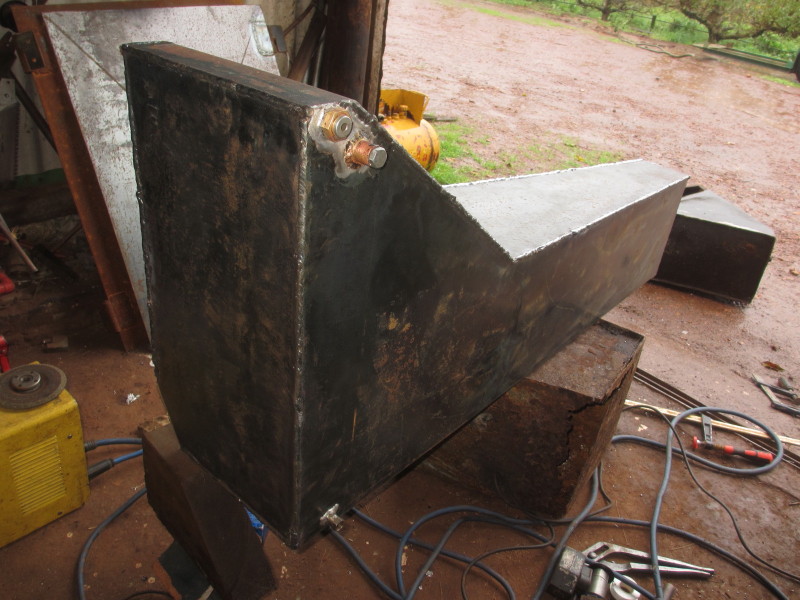
All the covers off, would it go in? Actually still not, but by trimming off the upper left corner of the radiator cowl, in it went!

Made to fit! There were two brackets bolted at the bottom which will need modifying because (thankfully, because the radiator and cowl are very close!) the tank is slimmer now without the insulating jacket. As it got dark there was just time to wire brush and rust-treat the edges of the big top cover. Now I can work out how to mount the air cleaner.

Now, to connect the fuel outlet and return hoses, add some diesel and hope there are no leaks! Before refitting the top covers!
:-) Andy
Fuel Tank and Other Jobs
19th June 2016
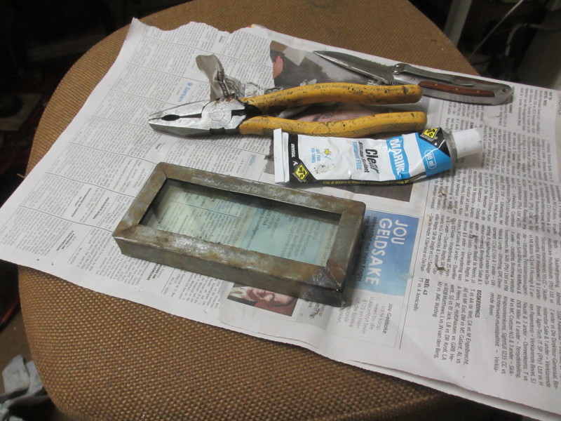
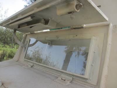
Last issue I showed a picture of the sheet of safety glass in the flap-up windscreen. It's loosely in place for the moment until all the spray painting is done.
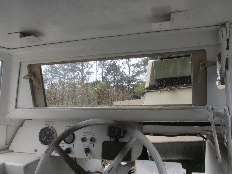
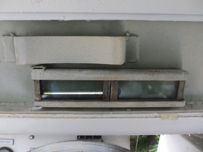
The other job to do with glass was to renew the thick glass which the driver looks through when the normal windscreen is folded down and the armoured steel hatch is lowered from above. There is a slit that the driver can look through and a head-rest (still to be padded) which the driver can rest his forehead against. In the hatch is a slide with space for two very thick (18mm) pieces of glass with metal surrounds. One is over the slit, and should that be damaged it can be removed and another is ready to slide across from the right.
I had to warm up the one corner that was lead-soldered to remove the old faded glass:
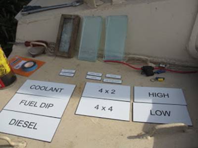
I asked the hardware shop to save the off-cuts from making the first sheet of glass and to make six small rectangles, three of which neatly made up the 18mm thickness.

Once the metal was all cleaned up, I simply applied clear silicone to the inside of the frame and closed it over the three layers glass, having cleaned them to the best of my ability!
During the week the overly-large tags for the remainder of the inspection / checking points were re-made, the suppliers accepting that the misunderstanding was theirs.
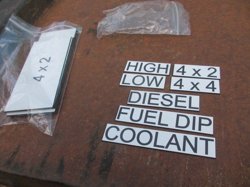
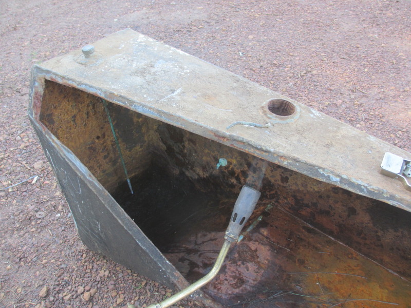
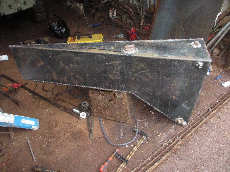
That's better! The next job concerned the DIESEL and the FUEL DIP tags: the new fuel tank! The little 27 litre tank I was planning to use really wasn't going to work and would need filling inside the fighting compartment with jerry cans and would lead to spillage and an unpleasant smell. Also 27 litres isn't a comfortable amount of fuel to drive around with. We decided to replicate the very rusty fuel tank over the left rear wheel-arch in the engine compartment. I was all for simplifying the shape which has to fit in with the contours of the sloping sides of the Car. At the steel service centre, the experts said, 'Just leave it here, we'll copy it!'
What arrived, cut and bent out of 3mm hot-rolled steel plate was beyond my wildest dreams, and very reasonably priced!
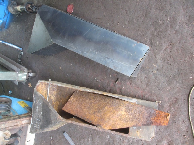
The extent of the rust inside the old one below can be seen! The new one was tack-welded together, except for the last big piece on the side. Where possible, edges were bent. All the plates fitted together with no gap at all, ideal for welding the remaining seams which could not be bent.
I first needed to find a filler neck and cap. There was only one cap and several necks, which I hoped were lead-soldered into the old tanks. I tried heating with a blow torch to melt it.
No such luck! They were brazed in place! The other very badly rusted 27 litre tank had the only cap, well stuck in the neck. With plenty of heat, and some persuasion, the cap came out.

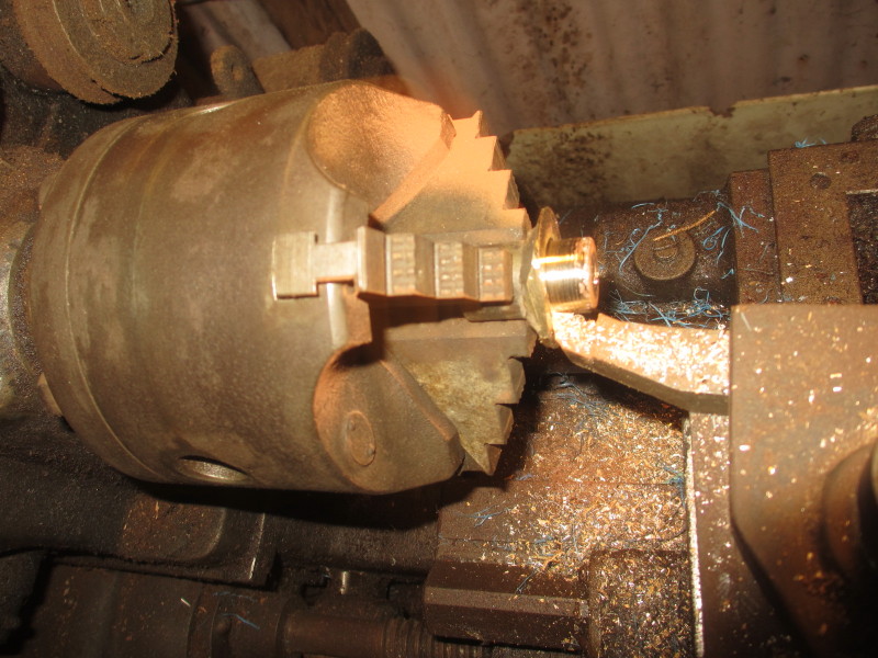
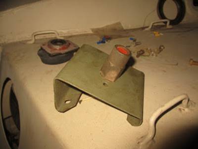
This neck protrudes higher than the fuel tank necks so it was easy to cut off above the top of the tank. It needed some fettling in the lathe. I cut a shoulder so that it wouldn't fall through the hole in the tank while soldering.

It was first necessary to measure the exact positions of the filler neck and the dip-stick, so that they would be accessible under the lids in the engine top cover. I cut the dip stick holder out of the old tank.

The two holes in the tank at the top were sizes I didn't have hole-saws for (typical!) but every time I need to buy another size, my range of cutters is increasing!
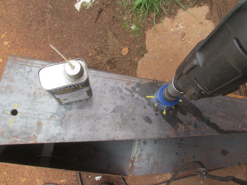
Soldering can be tricky, the surfaces need to be spotlessly clean, fresh metal, and although my big torch is good for laying the heat on, it's not good for heating a small area! Anyway I was pleased with the result!
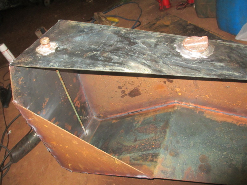
I wanted to do the soldering before welding the seams because quite a lot of solder falls through into the tank and it would be easy to clean out. But I knew I'd have to be careful of heat generated while welding near the solder! For the tank outlet and water drain I decided to weld first. It was also necessary to fit an adaptor for the fuel return hose.

The water (condensation) drain is right on the lowest point. The tank outlet is slightly higher leaving about a litre of fuel if the engine lift pump starts sucking air. The fitting also came out of the old tank and needed squaring-up on the lathe:
I welded all the edges first, with the exception of the last big cover plate. When I was close to the dip stick and filler neck, I welded a bit, then cooled the steel down with a wet cloth, then carried on.
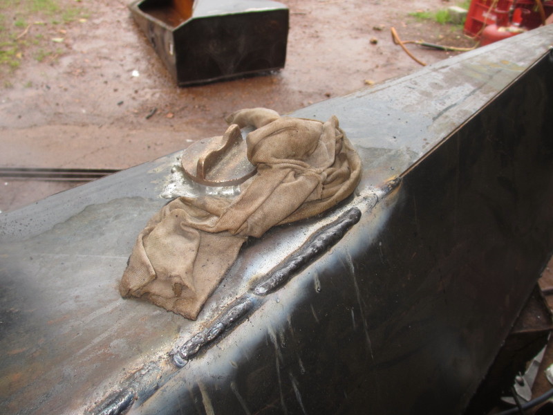
With the drain, outlet and return fittings soldered on.......
...... the next stage was to try out the large plate to close everything up.
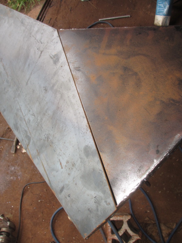
There was just one edge which didn't quite match. Perhaps the whole tank had 'pulled' while welding, but it wasn't too difficult to 'fill' the gap with a welding rod laid between the edges.
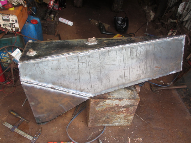
So, there it is, a brand new fuel tank! But will it hold diesel, which is known for finding a tiny blow hole? I will take it to the radiator repairers and have it tested under water with air pressure inside. If it leaks, they can either solder the offending place(s), or mark them and I can grind away and weld again.
In the picture above the flat side of the tank can be seen, which will be visible from the engine, with outlet, drain and return fittings. If I've done my measurements correctly, the filler and dip stick will be under the inspection covers!
Gradual progress...
12th June 2016
In the last report, the dashboard was shown loosely in place with the ignition switch hanging down. There was still wiring to do, particularly wiring up and refitting the assembled headlamps.

...... and connecting a hooter to the original bracket and wiring that up too.
I doubted that the earth would still work on the hooter button on the steering wheel, so I drilled another hole in the dash for a button before fitting the dash permanently. I assembled one of my convoy lamps, taken off a SWB FFR (Fitted for Radio) Land Rover I once owned and fitted that to the bracket for the right rear toolbox lid.
I couldn't work out where the oil pressure sender unit should be on the engine. I visited a friend with a Hyster forklift exactly the same as the one this engine came out of, and got the answer! It's tucked away below the fuel filter!

I could then connect all the wires behind the dash and was pleased to get oil pressure and charge warning lamps working. I coupled up the rev-counter too, and tucked the cable into the clips supplied for the original speedo.

The last touch on the dash was to have stick-on labels made for everything on it.

At the same time, I had others made for the transfer box levers and filling and checking covers at the back. They are a bit big, owing to a misunderstanding, but we'll have them trimmed down.
Also in the picture above are two sets of three rectangles of safety glass and on the left, one of the old holders for the resulting thick block of glass. When the front drivers flap is down in 'fighting position' he can either look through the slit, or slide one of two of these blocks of glass from a slide on the right, over the slit. At the same time, I had safety glass cut for the fold-up windscreen.
The last job on the wiring was to connect up the interior light in the fighting compartment.

There is still some work to do on the switch which is in the middle of the opening to the driver's compartment so any of the crew can operate it.

We have heard some good news: that a Team from the Natal Mounted Rifles Regimental Museum is busy restoring another Mk4! They had it at the Royal Show at Pietermaritzburg in May this year, with these information boards:


We need to make contact with them to tell them there are other Mk4s with their original Ford V8 engines, one at the Armour Museum at Tempe, it also came from the Boet Percival Collection in Bloemhof, and one or two at Ysterplaat Air Force Museum in Cape Town.
Also we have evidence that some of these Cars at least, left the Dorman Long factory in desert camouflage colours:

This copy of information about the Car was also on view.

I think 'early 1970s' is a bit too late. Certainly by the time I did my training at 1SSB in 1969, they had all been phased out completely, replaced by the French-designed and South African-modified Panhard AML 245, the locally made ones being called VA Mk 2 & 3 / 60 or 90 (depending on the armament), which became the Eland, or 'Noddy Car'.

Headlamps and Paint
15th April 2016
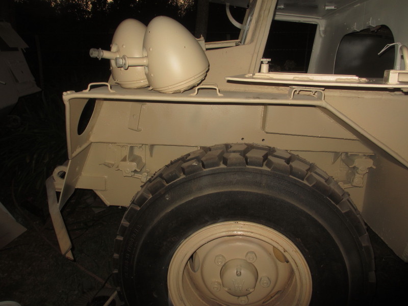
Only after I'd cleaned up and primed the headlamps as described in the post entitled 'Electric Wiring', did I discover I had two right hand lamps! You might think, what's the difference? But the lamps are mounted on horizontal stems and if they're the same, one will 'dip' upwards!

What now? I realised I'd gave to turn the lamp holder over somehow. First I removed the sealed-beam lamp and the cradle it lies in, the angle of which is set by two adjusting screws about 90° apart. I then ground the heads off four tiny rivets.

Removing the remaining part of the holder once the rivets were punched out, wasn't easy, hammering outwards, and rust was causing it to stick.

Once it was out, there was an opportunity to polish and prime where I hadn't been able to reach before. I then rotated the inner part 180° and refitted it, carefully realigning the rivet holes.

Instead of rivets, which I didn't have, I used 4mm machine screws, trimmed them off at the nut on the inside, then hammered the heads over, so that the bezel could still fit over them.

So at last, we have a 'handed' pair of lamps, the stems here are facing inward as they will on the Car, each lamp is the right way up and the setting screws (in yellow) are in similar positions.

By this stage, I was anxious to fit them and wire them up but just as with the dashboard, I realised there was painting to do first! I did a quick 'critical path analysis' (or in Army terms, a 'map-time appreciation') and got the compressor and spray gun out! First I had to clean and prime and then paint the underside of the wheel-arches. The weather was magic, no wind, warm, and ....... no flying bugs!
At the same time, I masked the glass of the lamps and painted them Desert Sand. Sounds quick and easy? It wasn't! At least now the lamps can be refitted and connected up to the dashboard, but I want to use a switch on the steering column as a 'dip' switch. It felt as if it was robustly built, it still clicks from side to side, but I didn't know what to expect inside, so I dismantled it.

Inside it is in good condition, it's very well made.

There is an input terminal (top here, but it's upside-down) and a large and a small output terminal. This means that there's always contact to the big one, the small one is additional when the switch is operated. No problem, both filaments can burn on 'bright'! I had taken the nose plate off for access to clean and paint. This will also make wiring easier for the lamps and the hooter.

At the same time, I realised I'd have to finish cleaning, priming and painting the remainder of the driver's compartment, so I masked off what I'd done already. You may ask why I didn't do it all at the same time in the beginning? The answer, as our Instructors would say when presented with a question they couldn't answer: 'Kak vraag, sit!'
Polished with the wire cup brush above. It should be noted that there isn't room to squat in the driver's position, the whole job of wire brushing, priming and painting has to be done through the hatches or from the fighting compartment, kneeling or lying back against the steering wheel facing upward!

With primer. The front and right hatches are blanked off so the primer wouldn't mess up the already-painted hatch covers!

That's better! While I was busy with the Desert Sand, I gave the inner faces of the right and left hatches another coat, as well as tidied up where the white and Desert Sand come together at the front.

It didn't really need this because it will be covered by the nose cone anyway! At least I can now compare this with a picture I got from the South African Airforce Museum at Ysterplaat in the beginning:

I think my colour is more accurate than theirs, not only from memory, this picture below was taken at Runtu in 1970.

Below, live firing on the Border on high angle, the 60mm mortar bomb drops as little as 35 yards in front of the Car, hopefully on the other side of an obstacle!

Also, while I had either primer or Desert Sand in the spray gun, I painted more panels of the other Car, parked right in front of this one, so that is gradually turning sand-colour!

It's now less than a year to the Event where this Car will make its debut, Stars of Sandstone '17!

:-) Andy
Old Photos, Papers and Badges Found
1st March 2016
Today some interesting items have turned up in my late Mother's possessions, more correctly my Dad's, which she had been holding on to for the five years since he died.
The first was the original photo from the very first installment on this blog, which I've been able to scan again:

This picture is special because it has confirmation of the people, Arthur Waks from Heidelberg. Western Cape on the left, Manus 'Pottie' Potgieter from Duiwelskloof, now Modjadjiskloof, Limpopo, on the right and Dad as Crew Commander on the turret. It also has the name of the Armoured Car 'Starlight', a place 'Gazala' and a date 20th May 1942!

This was nearly a month before the famous (notorious?) 'Gazala Gallop'.
Also from among the papers I found this 3 SA Armoured Car Recce Bn., 1941 Christmas card showing a Marmon Herrington Mk II.

It was sent by my Dad to his sweetheart, then in Salisbury, now Harare, my late Mother.

The Rhinoceros refers to Garri Kifarru which is the name of the Armoured Cars in Swahili. Ons Is (We Are) is the motto of the old South African Tank Corps. Here is Dad's beret badge which we also found.

Later he wore the badge of Natal Mounted Rifles, 'Rough but Ready'. We also found this badge.

Later in 1942, Dad was sent back to 'The Union' for an Officer's Course at Voortrekkerhoogte, and even had Christmas at home in Bonnievale, Western Cape. We also found this invitation to a school Old Boys' Dinner which was held at Voortrekkerhoogte on 4th November.

I wonder how many of the Old Boys who signed here survived the War?

R S M Wingfield, fourth from the bottom on the left didn't, he's on the Roll of Honour, so is D Tattersall, third from the top on the right :-( I can't read all the signatures.

The other thing we found among Dad's things was this tie:

The unassuming little triangles in gold bounded with green are those of the 6th South African Armoured Division, which was made up of all these units:

All under the command of General Evered Poole from its formation in February 1943 until the end of the War.
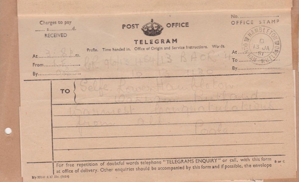
Just to show the gems we have found in my late Mother's papers, here is a telegram from the same General Poole, congratulating her on my birth! He was by then (1951) my Dad's chief at the South African Legation in Cologne!
:-) Andy
Electric Wiring
28th February 2016
I have been longing to be able to start as well as stop the engine from the driver's position! Last week I removed the old wires, and measured the length from dashboard to engine, nearly 6 metres! I knew I'd have to lay all the wires I need at the same time, there will be no chance to add a wire to the corrugated sleeving, mostly because it passes through a steel tube over the driver's right hand hatch.
I reckoned I'd need one wire for each of main supply to the front, the glow plug, the starter, one each for the ignition and oil pressure warning lamps and one for the temperature gauge. I added another for safety, and before I'd finished feeding them all into the sleeving, I remembered the tail light would need it!

I tied all the wires up at the dashboard end with plenty of slack, then fed the sleeving through the vehicle from the back, then through the steel tube and hooked the whole loom up into position. I had bought a new type of fuse to put in the main supply. I drilled and tapped holes to fix it to the bulkhead at the back of the crew compartment above the existing knife switch, which I'm using as a Battery Master Switch.
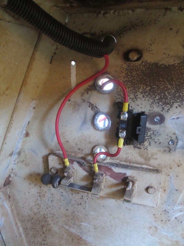
The main feed comes from the battery just behind in the engine compartment; the cable-grommets are made of beaten lead! I then connected everything up at the engine.

With just the ignition/glow switch connected at the front, I couldn't resist turning the key.... the engine started immediately! The next job was to fit the fuse box and light-switch to the dash and to drill and round-off two holes for the wires to pass through the dash above (in) and below (out) the fuses.

Then, to minimise the 'behind-the-dash' work, I prepared the wiring behind it. It will now only be necessary to connect up the wires on the warning lamps and the temperature gauge from the back and lights and hooter to the front.

I want to use the lamps from the other Car, so I took all four lamps off; they came off easily, which surprised me!

The ones with the sealed beams (one has a hole, the other is open circuit) came apart quite easily. They look like standard Lucas-type parts:

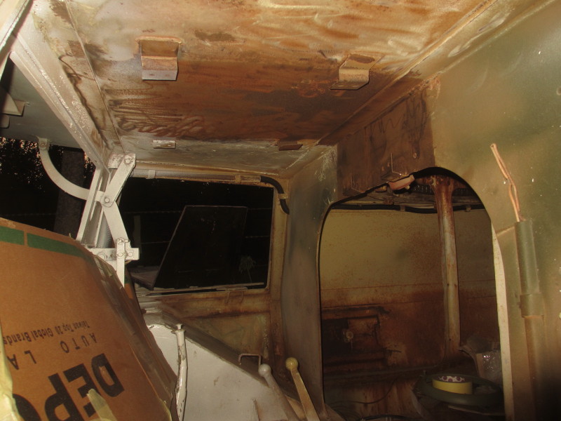
I realised it was pointless fitting the dash before I'd dealt with the wire brushing and painting behind it. I also want to use what I think is a dip-switch on the steering column and I couldn't get to the terminals behind it. It would also have been very difficult to lay the new wires to the headlamps from the driver's side. All this meant I had to take the nose-cone off this Car for the first time. I expected to battle with the bolts.... not so! It's probably easiest to top up the Brake Master Cylinder which is under the pedals, by removing the nose!
The inside of the Car didn't look pretty after I removed it!

Well, it was a lot easier to get in with the grinder and cup brush than from the driver's side! Soon it was looking much better with rust removed and a coat of primer.

With a coat of Plascon Synlac white over this primer, I'll be able to lay the wires for the headlamps (dip and main from the switch on the column) and the hooter. Then I can fit the dashboard!
:-) Andy
Steady Progress on the Perkins-engined Car
21st February 2016
At the end of the last episode, the Perkins-engined Car was parked up, out of the way for the duration of the fruit picking season. The other Car was still in the way in the middle of the yard.
Because I was still working on the wheel we'd removed the concrete from, I had to jack up and remove a wheel from the runner and put it on the non-runner. Oliver next door kindly came around with his CAT digger and pulled and pushed me into place in front of the other one in the driveway:
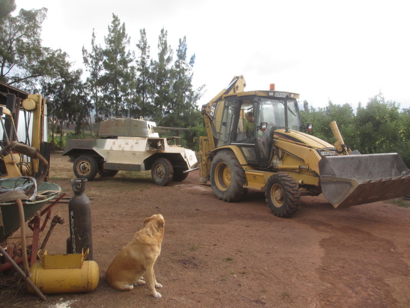
Without brakes and on a slope, it wasn't easy! A short video can be seen on this link
https://www.youtube.com/watch?v=j8Oo6Ixtw-s
Also in the driving position you have absolutely no rear view! It involved quite a lot of climbing in and out. And I thought climbing in and out of an Eland was difficult!

Now anybody arriving at the gate has a frosty welcome, looking right down the barrel of a 2-pounder anti-tank gun!

Eventually the tyre was removed from the wheel, mounted on a lathe and cut. A steel ring 80mm wide was rolled and as the welding cost a lot of money with the previous three wheels, I did it myself. The ring was tacked into position where the cut was made and I ground out a vee all the way around and welded with rods.

In a couple of places I 'blew through' so the penetration was good. I did the inner join first, then the outer, which I also did from the inside. In all, 29 3.15mm rods were used up. It remained to prime and paint it and to extend the slot for the valve.
With the tyre now on, at last I had 4 wheels on each of two Cars! The right rear wheel on the Perkins-engined Car is still full of concrete, so it must be swopped with the left rear one on the other car. Those wheels full of concrete are heavy!
The next job I can do easily where the Cars are parked now is the wiring and instrumentation. I had decided that a rev-counter was more important than a speedometer and both the old rectangular Ford instrument clusters had been badly damaged. I had a new plate cut to the profile of the old one, but with a round hole for the rev-counter which is for a Massey Ferguson which uses the same engine. I had a 3.7m cable made up to reach from the back of the engine, under the floor and through the same hole under the driver's position which the speedo cable had used. Here I'm revving the engine a bit! The needle is very steady.

I really need to be able to monitor the engine water temperature and I was unlikely to find a mechanical gauge with a tube over 4m long, so I have settled for second-best, an electric one. That needed another hole in the dash, and I need warning lamps for oil pressure and generator, an ignition/starter/glow switch with a key (Massey Ferguson part again!), a headlamp switch and a fuse-box. I also transferred the 2/4-wheel-drive instruction plate:

It might seem strange that the front wheels should be driven when the vehicle is in 2-w-d, but that's because the engine faces the back and the transfer box is also turned back-to-front.
Soon the new dashboard was looking like this (with the old one for comparison:

Loosely in position, it looks like this from the driver's position:

I then stripped out the old wiring. Over the right hand driver's flap, the wires pass through a steel pipe. I was amused that there was more sand than wire in the pipe!

I wonder which desert that came from! I am now busy laying new wires on the same route as those removed.
:-) Andy
Running under its Own Power!
5th February 2016
This is a busy time for us in the deciduous fruit industry in the Southern Hemisphere! Everybody is frantically getting ready to start picking, bringing tractors and trailers used once a year out of moth-balls and being a farmer as well as a farming equipment mechanic, I'm as guilty as the rest for leaving it to the last moment!
More important to me is that the two Marmon Herringtons are in the way! I was determined that the one I have fitted the Perkins engine into would move away under its own steam, and today it did! See this short clip to prove it! https://youtu.be/lgDngPEWp2Y.

But I'm getting ahead of myself! My last report was exactly a month ago. Looking through my 'to do next' list I finished off with, the accelerator control is done. I had a cable made to go from the end of the rod under the radiator to the fuel injection pump. I've freed-off the linkages on the rods between the pedal and the back and fitted a tension spring to hold it in the idle position.
For the shut-off, I used what was probably the choke control, a rod which the driver can reach just behind his right elbow on the hull floor. This has a long bell-crank lever in the engine room, the top end of which now has a rod connecting it to the stop control on the fuel injection pump, again with a return spring.
For the rev-counter, I managed to get an insert for the round hole in the rear of the camshaft. It is a hammer-fit in the camshaft and has a square hole in the middle to drive the inner cable.

Finding the correct cover with a thread for the cable outer was more difficult, but a used one was located.

The exhaust and silencer are made and fitted. I bent up one of the old brake pipes to more or less the right shape from the exhaust manifold to where there was room for the silencer / muffler. Gordon made that up first and I offered it up. With a little bit of modification it was fine. Another bent up brake pipe for the tail pipe next and a slightly tighter bend in one place and we have a simple and very effective system. I must still make a hanger from a convenient frame in the engine room.
I fitted a new CAV Thermostart / manifold heater and made up a new supply pipe for it from the fuel filter. I also blanked off an unnecessary adaptor in the inlet manifold and another in the timing cover in front.
I had stripped the left rear brake drum and dismantled the brakes and sent the slave cylinder for re-sleeving. Having found the left and right are identical, I stripped the same drum and cylinder off the other Car and the two cylinders went away together. I removed the old metal-and-leather hub seal and measured for a replacement. The suppliers just laughed when I gave them the inch sizes! We settled for a metric equivalent on the inside diameter, and had the metal jacket of the old one machined for this seal to fit.

It worked very well, although I didn't drive the seal in quite as far as it was before.

There's a cone attached to the brake back-plate to catch any oil that might get through, but strangely no place for the oil to escape where it won't contaminate the brake shoe linings! I rectified that by cutting a groove with the rotary file / die grinder:

Then the back plate could go back on. I couldn't find my box of split pins, so I went one better with locking wire!

So this drum could go back on. Being on the left side of the vehicle, the wheel-nuts have a left-hand thread.

The third widened wheel with the new tyre could then go on, making that side of the Car quite impressive!

I still need to widen a fourth wheel for this Car (actually two, counting the spare). All the remaining wheels have concrete in them from this vehicle being a static display at Bloemhof. I had tried hammering one tyre with a sledge hammer now and then and a bit of concrete came out but I could see it was mixed strongly! I rented an electric jack-hammer for the weekend thinking I could deal with all four wheels. Ha, ha!

I wore myself doing half of one! This also involved cutting more holes in the tyre with an angle grinder; not easy with rubber over concrete! I left the remaining concrete in the first tyre to my farm staff with just the sledge hammer and, yes! they got the rest out! To get the locking ring out was the next job, it was well and truly rusted in place and still jammed by the bead of the tyre.

I got it off, but would the tyre come off the rim? The jury's out on that one! I got a twinge of nostalgia when I dropped off one of the tyres at the recyclers:
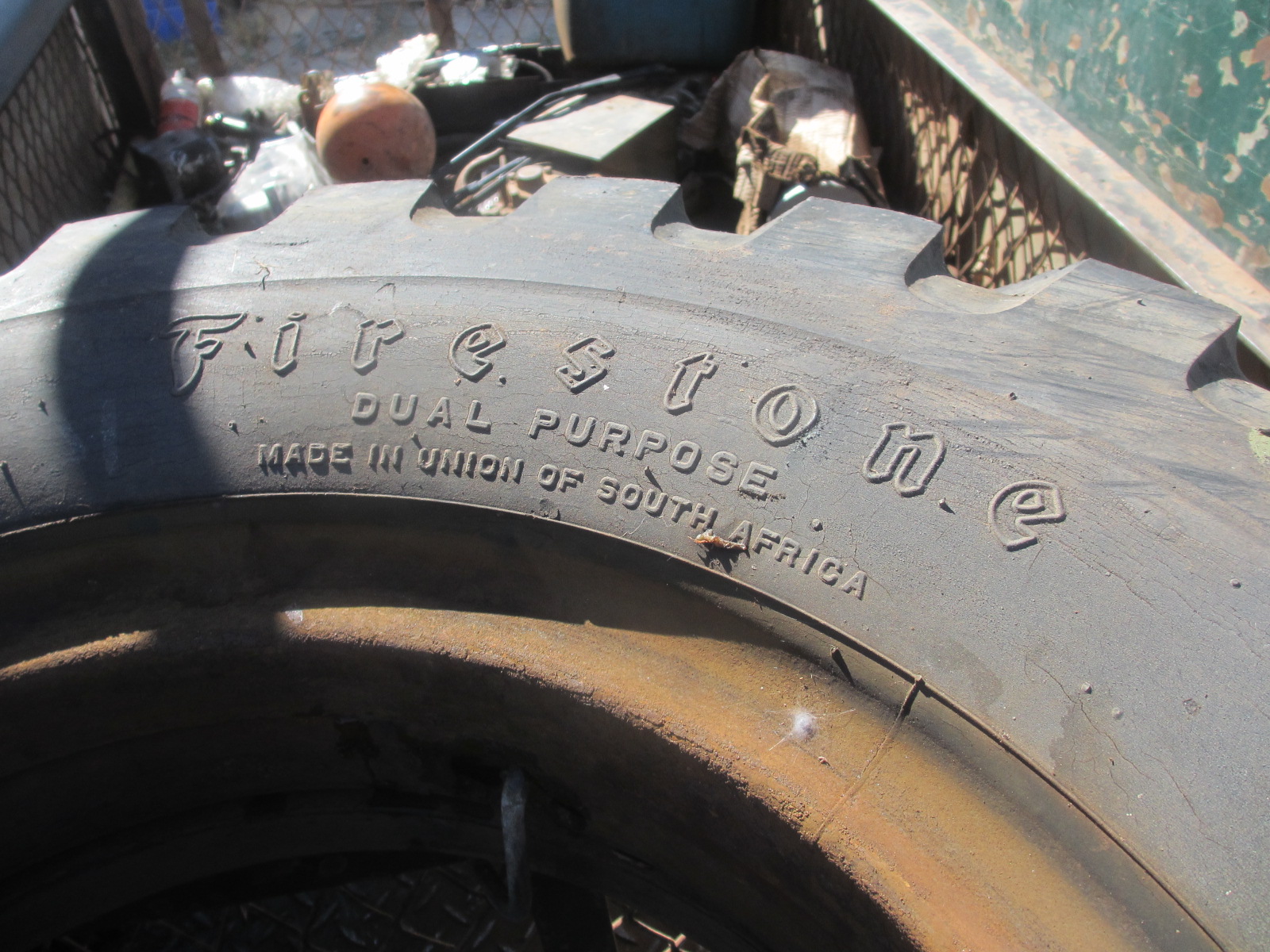
Firestone, Made in the Union of South Africa! We've been a Republic for 55 years!
In the meantime I had bled the fuel system, fitted a battery and connected up very basic wiring. With oil and water checked and with transfer box and gearbox in neutral, I operated the starter and off the engine went!

As usual there were leaks here and there, an air leak into the fuel system caused a missfire, but it seems to be running reasonably, if with a bit of smoke, shown here before the exhaust was fitted: https://www.youtube.com/watch?v=l-1D7Rb_wOU&feature=youtu.be.
So, with still one concrete-filled wheel, I was ready to go, but of course with no brakes at this stage! I thought the hand brake would hold, and working in 1st gear low, I found I couldn't steer quickly enough and just pulled the stop control before actually hitting the stem of one of my Golden Delicious trees! :-(

I was not happy! Anyway I started up again and reversed out and Pippa filmed me doing the epic first run under its own power, to park it up where I can still work on it, but it won't be in the way of harvesting. My neighbour has offered to help move the other one with his digger-loader.
This is the clip of the first part of the run.... the dogs aren't happy! https://youtu.be/0c7yGeIIH1g

:-) Andy
Perkins Engine Nearly Ready to Start!
3rd January 2016

I could then remove the armoured glass blocks, one broken, the other opaque, from the slides over the thin driver's vision slot. It seems one was kept in reserve, ready to slide across if the first was smashed. I could also swing the frame for the 'normal' windscreen up and down to wire-brush, sand and prime. The curved metal plate is for padding for the driver's forehead while he peers through the narrow slot while the bullets are flying!

Here the Perkins Car is getting greener, with Plascon UC 501 primer:

From the back:

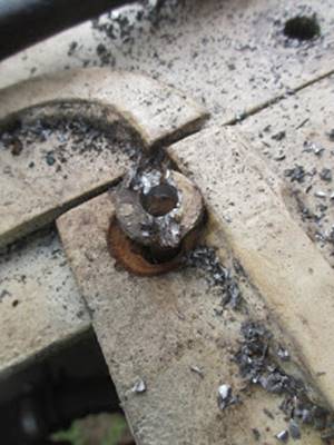
I was worried that the spare-wheel bracket was standing away from the back of the Car, so ground away at the heads of the bolts. At one stage the bracket popped away to show a thick coating of rust on both surfaces!
One evening, I realised that all the green primer was applied, so I got up early next morning and suddenly the Car was Desert Sand!
As before with the other Car, I used up the gloss Desert Sand as an undercoat and managed to use up a full five litres of the matt. I have been deliberating about the colour inside the wheel-arches. Looking at many pictures on the Web, they seem to be painted in the same colour as the rest of the Car. The other Car is black under the wheel-arches. I experimented with one where the wheel is off, for access to the brakes.

Inside, I started cleaning, but first I had removed the old tank previously used for condensing radiator water and pumping it back. It didn't look good!

Never mind, there was another I found loose in this Car, but when I inspected it, it had been used by bees as a hive:

Strangely the wax had not been 'stolen' by my own hive not 20 metres away. I checked with Matthew our bee man and he was worried this might be from the African Bee from north of the Cape Honey Bee's (Apis mellifera capensis) borderline . He asked me to burn it.

I then made a pick-up and return pipe for the tank and washed it out with diesel. First the space it had to go back into needed to be cleaned and prepared. Which desert does that sand come from?

There are drain holes at both ends of this depression in the hull, so I scraped and swept sand and rust through them and soon had impressive heaps!

I then got the idea to wash the inside of the Car out with the hose while the irrigation was on, a pleasant job when it was 30° C outside!

As soon as it was dry enough, I gave that part of the hull a good coating of primer and as soon as that was dry, the tank could go in!

I had previously fitted a fuel pre-filter and connected it to the engine.

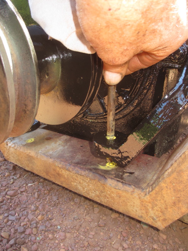
So what else was there to do before the engine could be started? I had removed the starter before to jam the flywheel to remove the crank nut to take the pulley off. I was able to jam it again to tighten it, so then the starter could go back on:

When I first lifted the engine cover at Sandstone, I noticed that one hinge had broken, presumably after the hinge-pin had seized. For some reason I only tackled this job after the Desert Sand had been applied! I thought it would be a simple job of welding two loops back on to the body and that the heat of welding would free it off. Think again! After the welds had broken twice, I eventually had to work downwards with a thin disc and cut the pin through in four places to remove the loops. It was hard work punching the remains of the pin from them and the remainder of the hinge on the Car.

The end result is reasonable and should last!

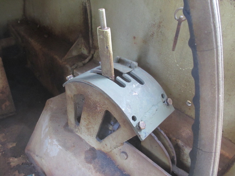
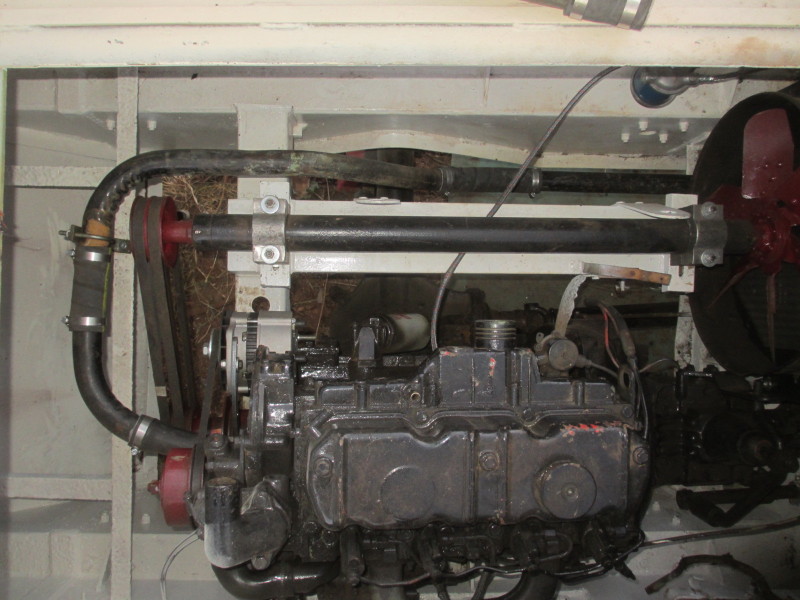
Another job I had been putting off was the gear-change, but I realised I had to sort it out before fitting the top and bottom radiator hoses for good (the top one is just pushed over to remind me to allow for it!) and the air cleaner. Working in the back means straddling the fan shaft with one foot on the chassis lip, the other on the diff and bending forward with your head under the armoured plate..... at 30+ °C! The gear-shift at the driving position has a gate and the lever position must correspond with the selected gear in the box.

The horse-shoe yoke is on a taper on the gear-shift itself. Theoretically when the driver moves the lever from left to right in the gate, the gearbox must be in neutral too. Not so easy! Perhaps with two people it would be easier, but every time I thought I'd changed the position of the yoke in the gearshift, meaning pulling it off with the makeshift puller in the picture above, neutral stayed where it was at the driver's end! Eventually, I added a piece of metal to the rear edge of the gate, moved it over forwards and drilled four new holes and fixed it down. No point in fighting! This will be a nightmare on the other Car!
I could then make up the lower radiator pipe out of pieces of the old brass tubing and rubber hose. A bracket was needed at the front of the engine. Luckily when changing the pipe around at the bottom, I noticed the dust-plug still fitted in the new radiator!
What next? Accelerator and shut-off controls. Wiring and instrumentation, rev counter and engine temperature. Air cleaner (I plan to use an original oil-bath which came with the Car). Exhaust; a silencer across the back, low down probably. Inlet manifold heater/CAV thermostart/cold start to fit and pipe-up. Brakes! Each wheel must be removed, drum off and brakes dismantled and slave cylinders sent away for sleeving. The Car is standing on dirt at a slope and the other one collapsed off axle stands! Even now the corner with the wheel off is supported on an axle stand and hanging from a chain block from the gantry! The inside of the whole Car must still be wire-brushed with the grinder, primed and painted white.
When the painting was done, Pippa suggested putting shade cloth up, what a difference!

Lots still to do! :-) A
Engine's In!
29th December 2015
It was good that it got too dark to carry on last night, it gave me time to think. The gearbox was fouling the bottom right hand corner of the new radiator cowling. 'Sarge' Hampton in Malta suggested applying Vaseline :-) but it gave me time to consider the options overnight. This morning I removed the fan and shaft and loosened off and swung the cowling anti-clockwise out of the way. Even then the gearbox fouled the bottom right hand stud, so I removed the stud completely.
The engine and gearbox could then be lowered first on to the rear (gearbox) mountings, and it was a bit of a relief that the studs on the front mountings dropped into the holes I'd marked out and drilled! I wasted no time refitting the rear mounting bolts, one with a nyloc nut, the other with a castle nut and split pin. It sounds as if it went like clockwork; far from it! At one stage I thought I was going to have to remove the whole assembly again and shave off some of the bell-housing!
Once in place, it was very satisfying connecting up the clutch release lever! One of the worries was whether there would be enough clearance between the diff and the sump. I needn't have worried!

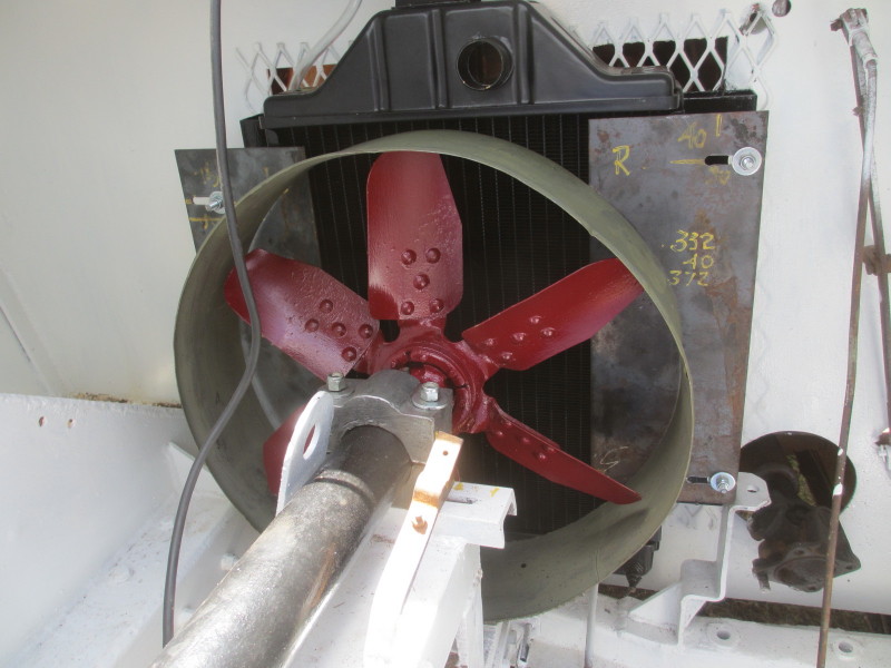
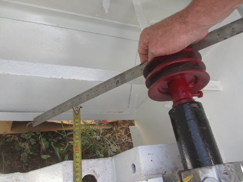
I then experimented with the fan pulley position and found that the best alignment was with the fan pulley assembly fully 'home' in the engine pulley. I measured and found two suitable belts in the village. The fan shaft and the engine crankshaft aren't parallel, so we'll have to hope the belts don't hop off!

Now that I was happy that the fan pulley should be all the way in, I removed the crankshaft pulley from the engine and drilled and tapped a hole for a grub screw and a register hole in the fan pulley assembly for it to seat into.
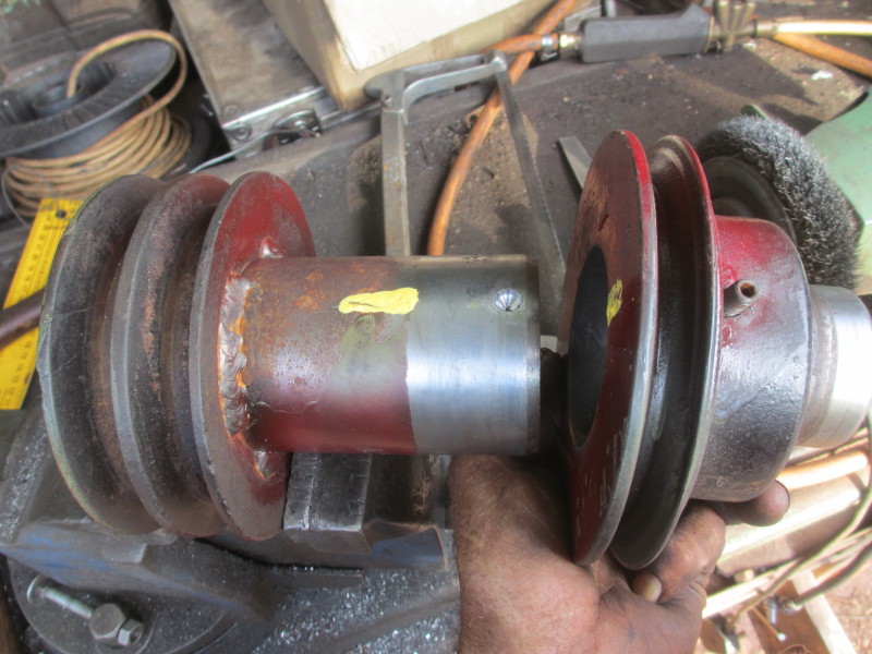
So both pulleys are back in place on the engine. While collecting the fan-belts, I bought a universal alternator, not being too sure how I would be able to fit it. On the Massey Ferguson 135 with the three cylinder engine, the alternator replacement for the old dynamo tends to stick out. Here on the 4-cylinder, I was very pleasantly surprised! Snug! I've measured for a fan-belt for that. The alternator can swing out a long way before it is likely to foul with the fan shaft or engine mounting bracket.

I made sure this alternator can work with an electronic tacho; it may be necessary to fit one. I know from driving the Eland, one needs to watch the tacho to change gear on the 'crash' gearbox.
Back to the fan cowling. I mentioned to Sarge it would be better to drill a new hole further up for the fourth stud. I trimmed off some of the bottom of the cowling, enough to swing it back into place and fixed it in position with the remaining three studs. I then drilled, from the crew-compartment, a new hole, also through a hole in the diamond mesh. The drill couldn't reach all the way through to the cowling, so I painted the end of the off-cut redibolt and pushed it through the new holes to touch on the cowling. The cowling was set about half-way on the other slots at the time. I removed the cowl and made a new slot:

I then cut the corner and the old slot away to make sure there was clearance from the gearbox and refitted the cowling and fan-shaft. With the alternator in place, I could start considering the top and bottom radiator pipes and hoses. The old engine had two top pipes and two between the bottom radiator tank and the two water pumps on the V8. They were brass pipes with all kinds of bends and elbows. One was absolutely ideal for the top:
 The bottom pipe will have to wait for the alternator/water-pump belt to be fitted.
Still to be squeezed in are an air cleaner, exhaust and fuel tank. I found an original oil-bath air filter in the crew compartment under the floor, so it might be a good idea to use that. Also in the crew compartment was this loose tank:

It is in perfect order and I realised that it didn't belong in this Car, there is already one, I had to remove a floor plate to inspect it:

These are actually the condensing tanks for the cooling system, there was a pump to manually pump coolant back into the radiator header tank. I have now measured the complicated shape and calculated that it has a capacity of 27.5 litres, possibly quite enough for the use we intend for these Cars with much more economical diesel engines! If not, there is plenty more space in the crew compartment under the floor down both sides, something I hadn't considered before.
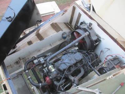
So this is what it looks like now:
And a flashback to how it looked when I first set eyes on it:

Made to fit! How the Greek Army managed to fit a 6-cylinder engine.... I just don't know?!
:-) Andy
Perkins Nearly In!
28th December 2015
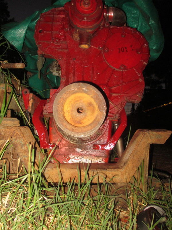
I fired up the old Hyster 3-wheel forklift and lifted the Perkins and gearbox off the frame from the other Car. I decided the flaky red paint was too scruffy.

So it got the primer treatment, Plascon UC 501 is my favourite.

The weather was hot with a slight wind, so I didn't have to wait long before I sprayed over a coat of Medal black. It's cheap enough, but does take a while to dry!

I picked out the pulleys with the same red I used for the fan and its pulley. Then I realised that I wouldn't be able to drill the holes for the front engine mountings after the engine was in place, and I couldn't measure from the front to the back mountings on the engine and gearbox; the bell-housing was in the way. The only way out I could think of was to lower the assembly back on to the frame from the other Car again and mark that one and then lift the engine off again and do some measurements on the frame.
I dipped the end of a long bolt in paint and inserted it through the holes in the engine mountings. I lifted the engine and gearbox off again and made measurements, straight and diagonal.

I could then mark the holes in the Car which the Perkins is going into.

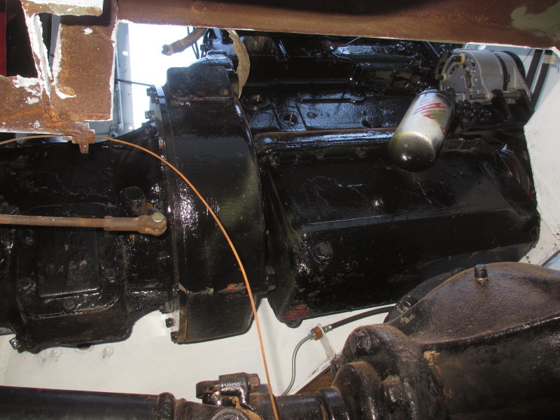
Before refitting the repaired prop-shaft for the back axle I started freeing off the levers and linkages at the back of the transfer box. This involved freeing off the stuck levers at the driver's end! I pulled out the input shaft (top right in the picture below) and withdrew the pins on the 2/4-w-d lever and the double-bell-crank for the clutch (on the left).

Once again, I thought this area looked scruffy, so I climbed in under the Car with the little grinder and a cup-brush and transferred most of this muck onto my face and into my eyes! I had been a bit hasty refitting the prop-shaft so I had to wrap that before first brushing a coat of primer on, then spraying another layer.

When that was dry I followed with a spray coat of the same white I used for the engine room, then picked out the levers and their brackets and rods in black. At that stage I refitted the input prop-shaft, ready for the engine. In the picture below, top right is the gearshift rod, slightly to the left at the very top is the hi-low control rod. I've managed to get that into neutral so if the gearbox is in neutral too, I can turn them and connect up the flange. Then the long lever is the 2/4-w-d, then the repaired shaft between the transfer box and the back axle. The remaining double bell-crank lever and shaft is for the clutch. All grease nipples (6 in the view below) are open accepting grease and everything is freed off.

I brought out an old trolley I made years ago for pulling stationary engines around and lowered the old V8 on to it and wheeled it out from between the Cars. Kerneels helped me push and pull the Perkins and gearbox back, hard work up the incline!

So the next step was to lift it with the chain block. Oops! The chain block's at its limit and the engine is not high enough!

Vivid reminder of the Seven P's!
Nothing for it but to lower it all the way down again and shortening the sling and winding it all the way up again, cursing my stupidity!

There was still some preparation to do before lowering the engine and gearbox into place; new brake piping and a hose to the rear axle to fit:
Another job was to close over the hole where the hydraulic pump had been on the Hyster which this engine came out of. There were some ideal off-cuts from the fan cowling. I made a template out of stiff paper and marked out:

Then cut, drilled, countersunk, primed and painted. I used the template as a gasket and fitted it. The old oil supply pipe to the hydraulic pump bearings had been folded over. I removed the whole thing and blanked off the hole with a plug.

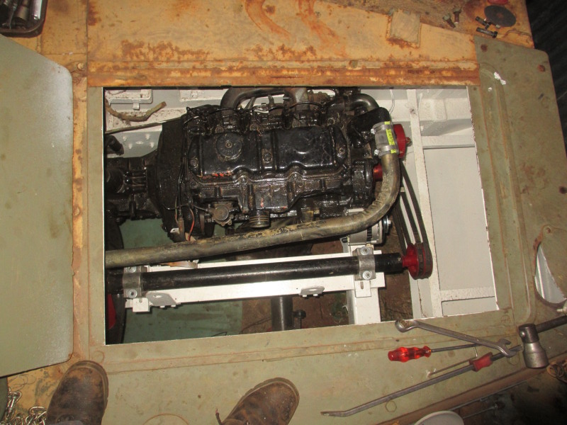
So, the next operation was to put the engine and gearbox in! Anybody got a shoe-horn?

Luckily I could still pull out the extension pulleys for the fan so that made the assembly a bit shorter. At one stage I had the gearbox stuck on the battery box and the engine on the fan shaft and thought I'd have to remove a lot more of the armoured plating. But by slinging it at a slight angle, I managed to feed it in, gearbox first.

Then with another chain block to pull it forward, I could get the gearbox mountings very nearly into place.

Just half an inch from its final position, I found gearbox pushing against my new radiator cowling! Nothing for it but to lift the engine again and to slack off the horizontal chain block to give enough clearance to either cut a sliver off the cowl in position, or to remove the cowling. Job for another day, it was getting dark!
:-) Andy
Preparations to Install Perkins Engine
24th December 2015
I mentioned previously that the Perkins engine and gearbox assembly is more or less ready to install. I was busy making up a copy of the left front engine mounting bracket. I heated and bent the steel profile I had cut half-way through and tested it in position. I was happy with the angle, so I tacked on a steel bar to prevent the bracket from pulling any straighter while I welded the gap I'd cut open to bend it.

I drilled a steel disc for the foot and welded that on to the end, square to the upright edge. The bar could then be removed and with a coat of primer, it's not easy to work out which is the new one!

In position, I was very happy with the result:
I sent the prop-shaft with the bend away to Ferobrake for repair and that is now ready to refit between the rear diff and the transfer case.

Then the next big job was the radiator. To have re-cored the old Ford V8 radiator would have been too expensive, so I settled for a new radiator from the aftermarket tractor suppliers to match the engine, in this case a Massey Ferguson 165 which uses the same engine. There will be no forward draught in this case, the air is drawn from the crew compartment, but then again a tractor is made to stand still and work!

I offered it up in position and lined it up with the filler opening above and made some measurements. I wanted to block off the mesh completely to at least reduce engine noise for the crew. I settled on two rectangular tubes which I bolted to the tapped holes in the front outer edges. The large holes are there for access to the heads of the bolts.

I needed to make sure that the bolts holding the assembly to the fire-wall would go through gaps in the mesh, so I marked suitable places to drill through the mesh, to go through the edges of the fire-wall.

Here it is in position from the crew's side:

.... and from the engine side:

The filler neck is easy to get to through the inspection cover. The turret has to be turned to one side to get to it from the outside.

This radiator will be cooled by the original mechanical fan, driven by belts from the front of the engine. The fan shaft is supported in aluminium blocks. Here I came across a problem, they were made back then as non-interchangeable pairs, top and bottom and the four parts I have to work with were mismatched!

With a bit of mixing and drilling holes oversize I was able to say I had two pairs which would work together, so I marked them to avoid errors.

The fan shaft could then be tested in position.

Well it doesn't help to have a fan whizzing around in empty space, it would need to be in some kind of cowling to make a positive draught through the radiator. Here was a hitch, the whole fan shaft is made to move to the side to tension the fan-belts at the drive end! Clearly any cowling worth its salt would also have to move from side to side. The full adjustment on the fan shaft is 30mm. I started making the cowl by cutting a ring from a 44 gallon drum and overlapped it to make a smaller diameter. I allowed about 12mm (½") all around.

Now the ring had to be attached to something and with steel yards closed for Christmas, I luckily found some steel plates left over from another project. I measured the mounting bolt spacing and started marking and drilling to make the 30mm-long slots.

Today, Gerrie De Jong arrived to help! We met at Sandstone Estates many years ago, he also collects stationary engines and he brought along an early style of computer screen/monitor with a pulley and shaft disappearing into it, driven by a little Fairbanks Morse 'salt-block' engine. It certainly drew the crowds!
We started by replacing the four bolts holding the radiator in place with longer studs. The two steel plates could then be bolted in place, with all slots adjusted fully to the left; fan shaft as well as both plates.
I tried welding the ring on to the plates but it was a failure. We also decided that the plates needed support from one to the other. There were two more plates from the other project! We slid them in and marked and measured, took it all out and did some cutting and tacking together.

Surprise! It still fitted on the slots! Time to weld and cut out the excess.

We made six little angle brackets and welded them to the plate and bolted the ring to it. We didn't want any bolt heads sticking out on the radiator side. Here Gerrie is pleased with the result!

I took it out and gave it a coat of primer and paint. Up to this stage we had been testing the assembly at varying distances from the radiator core. Once we were happy, I measured the distance from the rectangular tubing and cut four steel pipes as spacers. I squared the ends up on the lathe:

... and then assembled them:

Then the cowling could go in for good:

We did some measurements on the waiting engine and compared the position of the pulleys on that and the framework it is standing on now and we were very pleased that the fan will be close to the radiator and nicely inside the new cowling when the pulleys align.
A good day's work!

:-) A
Back on the Job!
6th December 2015
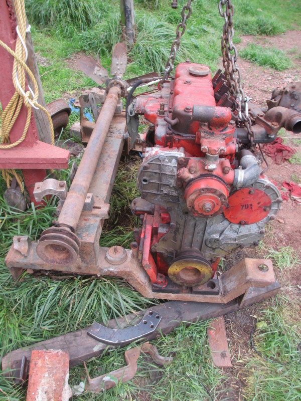
Back at it! There's been a huge amount of work to do on the farm, in the limited time I have here away from my Day Job(s)! One important one was getting at least one of my forklifts going so I can move the first engine (the Perkins) from where I offloaded it with a chain-block and assembled the flywheel, spacer, clutch, adaptor plate and gearbox on to it. At every stage, it's become heavier!

This is the Perkins engine which will be the easier of the two to install, and it's more or less ready to put into one of the Cars. I still have to make up an engine mounting on this corner. I had a flat piece of steel profiled; now I need to bend it to fit between the sump, timing cover and the mounting bracket from the Car. This bracket is the one I'm not going to be able to use with the Ford engine, so I'm just using it as a mock-up. I'll heat and bend the plate along the kerf I cut which can be seen in the picture below.

With the engine and gearbox nearly ready to install, it meant a lot of preparation was needed in the engine room on the Car. Cup-brushing with the angle grinder, a coat or two of primer, then two brush coats of white (to get right into the corners), followed by a blow-over with the spray gun.

The prop-shaft of this one was bent at some stage, presumably with lifting forks, or maybe it bottomed-out on something. Today I removed it; it will need re-tubing and new universal crosses.

While I was under there, I thought I'd drain off the transfer box oil. What I thought was the drain plug is in fact a very rotten rubber mounting, so there's another job to add to the list! There's a lot of old dry oil around, so I suspect there will be seals to replace, too.
When the white paint had dried (the weather was very hot, so that didn't take long!), I was able to paint the rear axle black.

So this engine room (for the Perkins) now looks like the one which will have the Ford engine in it:

The brake pipes and hoses which have been made up (in the picture above), can be assembled now that the painting is done, and before the engine(s) go in. It can be seen that the engine/gearbox mounting bracket is not in this Car, I will have to work completely from scratch with mounting the Ford engine and gearbox.
While I had the spray gun out and with good weather, I started spraying over the primer on the Car which will have the Ford engine, panel by panel. This paint is too shiny, but it's ideal to use up as an undercoat. I have had a tin of the same 'Desert Sand' mixed up in a matt finish.

Not a lot, but it's progress at last after a long gap!
:-) Andy
Two More Books of Wartime Photos
20th September 2015
Two more books have come to light, the first also from Hencoe Hunter, by a long-standing Friend of the Sandstone Heritage Trust, Les Pivnic from his Photo Journal No 10, also like Ons Stryd Teen Afstande, South African Railways' part in the War Effort. You can tell the photographer was more interested in the locomotive, but it shows a rare view of two Marmon Herrington Mk 2s or 3s, before their turrets were fitted.

Les gives his permission for this picture to be reproduced, but says it's the only one he has of a Marmon Herrington and unfortunately there was no other information with the negative.
The other book which Hencoe lent me, but which I already have a copy of, is the excellent book, South Africa in World War II, edited by John Keene of the SA National Museum of Military History. It contains several photos of interest to this story, unfortunately none of the Mk4s, yet there is a photo of the rare (only?) Mk5 under construction at the Johannesburg Tramways!


The rest are from East Africa or Madagascar. Here, two very early Vickers MG-equipped, rivetted Cars are seen 'negotiating the bushveld':

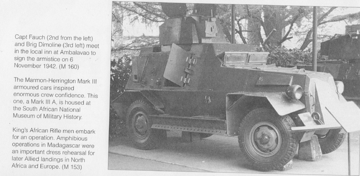
This Mk3A is at the SA Museum of Military History and shows a hull side door, glass 'windscreens' and a slot in the mantlet for a Browning, by the looks of it.
This picture says that the SA Armoured men are planning their next moves. Posing for the camera more likely!

This is from Madagascar, No 1 SA Armoured Car Commando being inspected.

The advance from Majunga:

:-) A
Two Wartime History Books
6th September 2015
There has been no mechanical progress on the Cars in the last week, we have been stone-milling wheat all weekend in support of Bot River Spring Weekend!
However, on Friday, local mechanic Hencoe Hunter lent me two books in connection with South Africa's involvement in WW2. One is called Springbok Record, by the familiar name Harry Klein, my late father's commanding officer during the East African campaign, then a Major in charge of No1 South African Armoured Car Company, later 3rd Recce. Naturally there is more detail concerning that period of South Africa's involvement in the War than the later parts; Western Desert and Italy.
The Marmon Herrington photos are therefore of the earlier Mk2 and 3s, with the engine up front. Nevertheless, it is worth adding them to this story. As Dad mentions in his own book, Story of My War, the colloquial name amongst the Swahili speakers was Garri Kifarru, or Rhinoceros Car. This from Harry Klein's book:


Here they are seen at El Gumu:

Here below, several Cars can be picked out by all the brushwood attached to them as camouflage! They are about to enter Somaliland on 24th January '41. My Dad wrote that at this particular stage he was displaced from his position in his Car by an unofficial 'camp-follower' who did chores for them in exchange for food or cigarettes, one Ahmed Said, also known as 'Armoured Side'. I presume he was more easily hidden from the Authorities inside the Garri Kifarru than in the passenger seat of a lorry which is how Dad entered Somaliland!

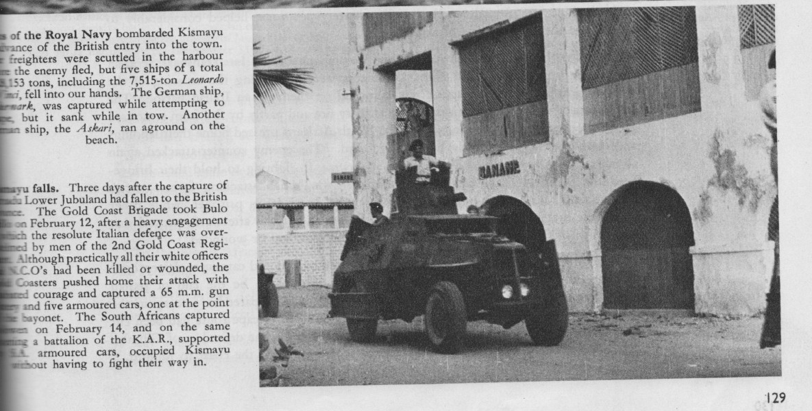
Here is one taken in Kismayu on the Somali coast, which fell to the Kings African Rifles, supported by South African Armoured Cars on 14th February '41.
Chasing the retreating Italians north of Addis Ababa, the South African Sappers had to repair blown roads and gullies. Here a Car negotiates a rock-filled obstacle.

From there to the Western Desert. This picture is titled Wardens of the Desert..... 'the Armoured Cars kept a close watch over enemy movements and were always on the spot to forestall any German surprise attack.'

Sidi Rezegh, at the tomb of the Arab saint of that name.... 'Under a rain of shell and bombs, the 5th Brigade Armoured Cars carried out daring reconnaisance during the day of the battle. The Armoured Cars reported the movement of large German tank formations towards the Brigade position. All that long day the enemy drove in attack after attack on the resolute Springbok defence.'

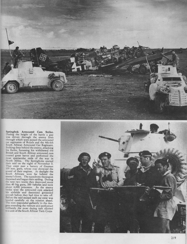
Then El Alamein in early November.... 'the British and South African Armoured Cars created great havoc and performed the most specatcular raids of the war in North Africa. The Springboks started their raid on November 3rd. They crept past a battery of German 105mm guns, whose roar drowned the sound of their engines. At daylight, the South Africans were far behind the enemy's front. The squadrons thereupon dispersed and began their raiding. During the next two weeks they destroyed more than 40 big guns, 350 vehicles and took about 6 000 prisoners. As the enemy broke west the Armoured Cars attacked his airfields and destroyed grounded aircraft before they had time to take off.......'.
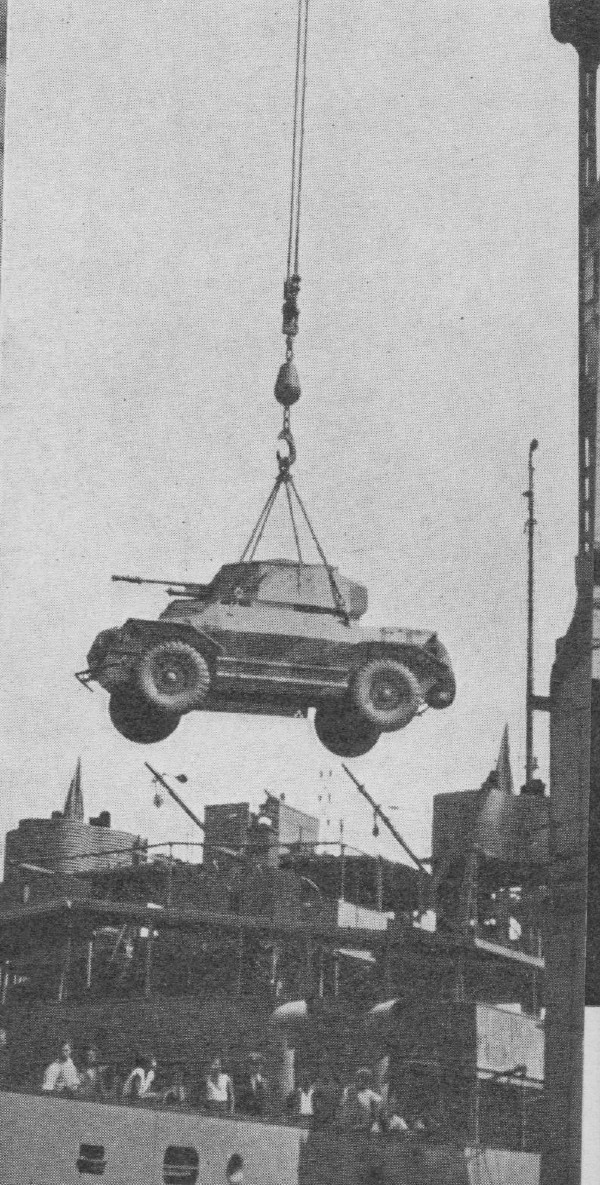
The other book is called Ons Stryd teen Afstande (Our Battle against Distances) about the South African Railways' part in the conflict. I have read, for instance that their bridge building teams were completing bridge reconstructions in Italy as the Allies were following the retreating Germans, at the rate of one a day for several months! Here a Mk4 (F, I think, from the lifting lugs on the hull) is suspended from a dockside crane. SAR operators were involved in captured harbours in North Africa and Italy.
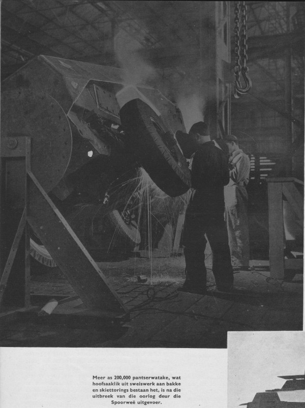
Here a welding operation is being performed in a Railway workshop on the right rear of a Mk4. One can make out the removable panel for access to the engine's left hand exhaust manifold (the engine faces the rear.) It can be seen that the hull is attached to a fixture in which it can be rotated to avoid difficult vertical welding. The mudguards and lockers must still be attached.
A row of completed Mk2s or 3s:

While this picture has nothing to do with Armoured Cars, it has a special interest. The caption says that ten thousand complete mortars were built by the Railways workshops.
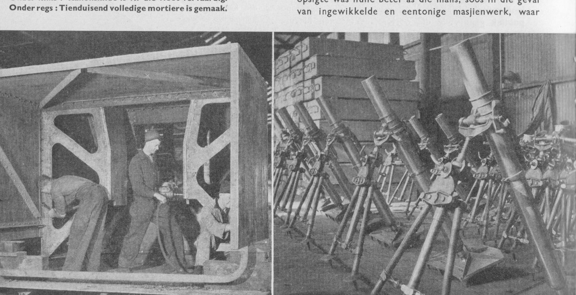
Small wonder then, that my friends in Malta have found a 3" mortar base with a South African marking!

The pheon is inside the U for Union (of South Africa)! It is dated 1943.

:-) Andy Selfe
Testing Wheels and Modifying the Third Widened Rim
30th August 2015
I had some time yesterday to put the first two wheels on one Car and to jack it up and turn from lock to lock. In short they are a great success!

Left hand wheel, from the side. Made to fit!
There was a catch on this one, one of those studs has a right-hand thread! I will have to mark it somehow. The wheels have been widened so I was worried that they might stick out, again, they look made for the job!

Both wheels on, dead ahead. Getting the concrete out of the two I took off will not be fun!
The next concern was that they might foul with the springs, wheel-arch or particularly the steering drag link. No worries there.

Clearance between the tyre and the steering drag link
At full lock, admittedly it doesn't turn sharply, it looks the part!

Left hand wheel on full lock to the left
The original tyres were 10.00 x 18. These are 12.5/80 x 18 Armour Rock and in a word, I'm delighted with the result! We have widened the rims outward by 80mm to 9". These tyres are marked that they are made for 9" rims. A word of warning, after the size, they are marked NHS, which stands for Not for Highway Service. That is of no concern for us but it might be for others who intend using them on the road.

Right hand wheel, straight ahead
Having now satisfied myself these wheels and tyres will work, I could then deal with the third wheel which was widened for us, but for some reason it was only necessary to widen it by 50mm instead of 80mm to get to the required 9". The other difference was that the dish of the wheel was in the wrong place, in relation to the rim. Luckily, the dishes are riveted to the rims, so I set the drill up at its maximum height and first drilled a pilot hole along the length of each of the 15 rivets.

Set up to drill at the maximum height of the drilling machine
Another lucky break was that there was a slight dimple in the middle of each rivet on the outside, so it wasn't even necessary to centre-punch!

Drilling pilot holes, the rivets each had a dimple in the middle so it wasn't necessary to centre punch them!
Gradually selecting bigger drills, I eventually broke through the first rivet at 11.5mm. Then I could drill the remaining 14. The heads were pushed out inwards by the drill.

Drilling the rivets out
When they were all out, I attacked the dish inwards with 14lb sledge hammer. It gave up without a fight and I was able to tap it all around until I had the same dimension between the dish and the outer lip of the wheel rim as the other two. I then bolted the rim back to front on to one of the front hubs and turned it, checking against a fixed register clamped to the spring. By tapping where I had the most run-out I got the rim so it had about one or two millimetres of wobble. That should be accurate enough!

Turning the wheel against a fixed register to true the rim to the dish
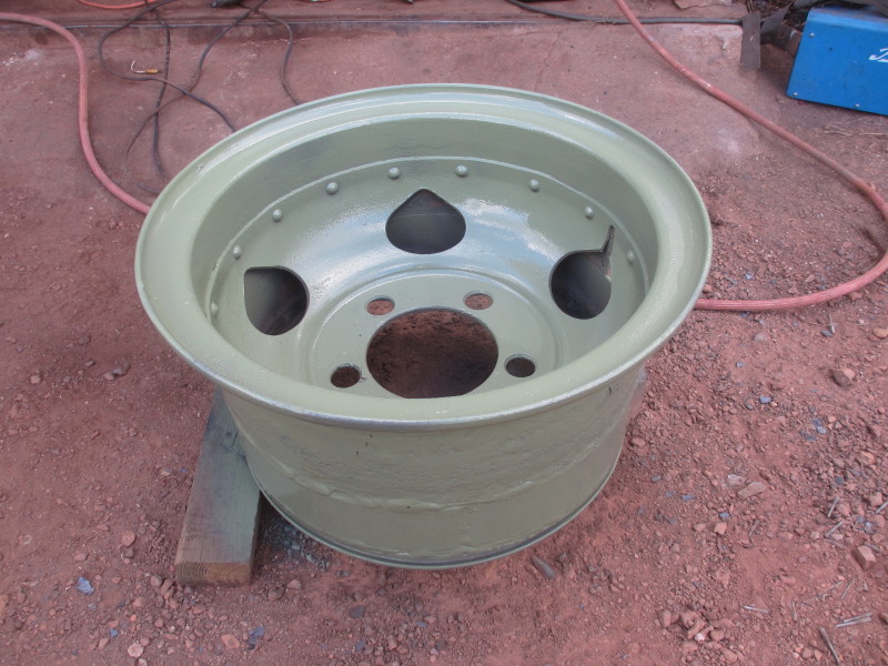
The dish was then facing outwards and I welded the outer edge to the rim, tacking first in four places. I also welded through each of the rivet holes on to the rim. It remained to prime and paint the wheel and locking ring so the third tyre can be fitted tomorrow.

Wheel with matt Desert Sand
This is now the matt Desert Sand paint. It's too soon to see how it will turn out, let's wait till it's dry!

First Wheels, Perkins Engine & Gearbox
23rd August 2015
The first two tyres have been fitted to wheels. They tell me the paint on the rims helped the beads slide outwards.

They look the part! I will first jack up the front of this Car and fit them and test full-lock to full-lock with maximum tilt of the front axle each way to make sure nothing fouls. The way I'm progressing, it looks as if this Car will be running first anyway! (That means I must give the brakes attention soon!) The two concrete-filled wheels I take off here will be the next headache! The third wheel which has already been widened is another headache, the dish must be moved across to match the others.
The spacer tube to hold the pilot bearing in place was machined in the week, so I could do a lot more on the Perkins engine.
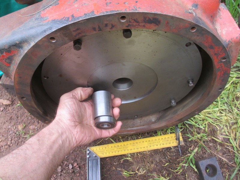
My sums worked out, with the outer face of the bearing 10mm below the clutch face. I could then assemble the clutch, aligning the driven plate with the primary pinion from the 'scrap' gearbox.

I put the pinion back in the gearbox; you never know when it will come in handy! I then tried to refit the gearbox and adaptor plate together, but it was too heavy and cumbersome. No problem, I put the adaptor plate on first, then the gearbox on that.

In the white engine room, all original parts will be painted black, the non-standard, in this case, red. At this stage, considering whether the engine would fit in the mountings, I had the idea of testing it in the engine sub-frame I removed from the Car which will have the Ford engine.

Nearly, but not! There was no harm cutting away at this frame, it's not going to be used anyway. After cutting away about 20mm, the engine dropped in.

Now it looks made-to-fit! Unfortunately the left hand engine mounting was missing. I have had a thick steel plate profile-cut, it's lying in front of the engine, but I'm hoping to get an original part from a forklift which was in a factory which burned down a few weeks ago!
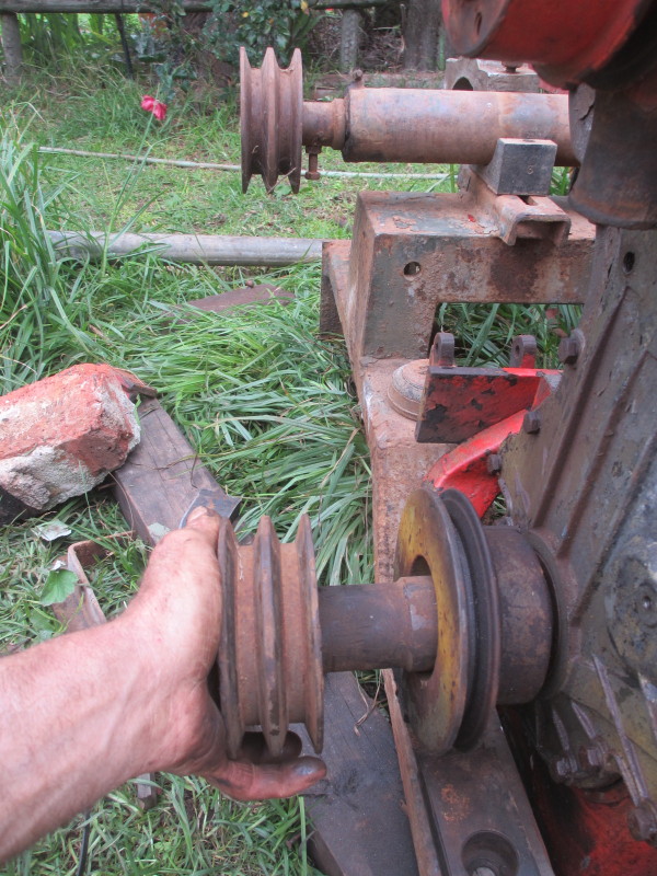
The other advantage of testing the engine in the sub-frame is that I can now work out what to do about driving the fan-shaft. I managed to take the double-pulley off the old topless Ford V8 and it won't be difficult to make it fit the Perkins pulley.
The inner diameter of the Perkins pulley isn't accurately machined, so I'll have to take that off. First I must measure carefully the distance the pulleys must stick out.
So there wasn't much more I could do on the Perkins, so I got on with preparing the engine room for it. I mentioned I'd need to dismantle some brake pipes in one corner, to clean up and apply primer, but before that, I cut out the sub-frame on this Car, as I had on the other one.
I will have a steel plate cut and bent to fit and weld it in there.
So, the pressure is on to get the Perkins engine and gearbox into this Car. The gantry is over both Cars and the other one is hanging from it. David, who donated the Perkins engine to the project, said he was sorry he had sold his gantry with his farm. The good news is the new owner who is a friend and customer of mine, has no use for it and has given it to me! I can straddle this Car with it and lift, move the engine and gearbox across and lower it in, in complete control.
:-) Andy
Perkins Flywheel and Painting
16th August 2015
The weather on Saturday was fine but the forecast for Sunday had 10mm of rain. I've been concerned about rain getting in on the workings of the 2-pounder, so I bought some self-adhesive sponge strip for the top covers. But these were still in primer, so I painted both covers, inside and out. It was so fine, sunny and windy that the paint was almost drying on the brush! Last thing Saturday evening, I applied the sponge strip.

The drizzle had started and on Sunday morning it looked dry inside! I am happy with the colour, but I'm investigating the availability of the same paint in matt finish.
The other painting job which I'd been putting off was the preparation and painting of the right hand sides of the hulls, where all the clips are for attaching the tools; spade, pick, gwala (crow-bar) and axe. The wire-brushing was complicated around all the brackets, and the springs and over-centre clips themselves.

After a couple of coats of primer, this one was looking better:
With the aid of the Manual from Gerrie last week, I could do a 'dress rehearsal' this morning! Who put the axe away broken last time?

The other painting job also involved plenty of wire-cup-brushing; the engine room for the Perkins. I had removed both rusty petrol tanks last time and what was left was not a pretty sight, although not as bad as the other one!

By this evening, it looked a lot better! There is still one corner to clean up and prime, again I have to remove brake pipes which are in the way of cleaning properly.
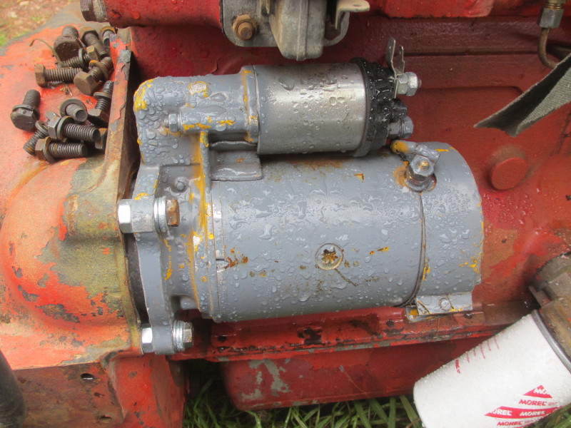
So now the Perkins engine is the focus of attention! Today I refitted the flywheel, first applying plenty of grease to the seal. This flywheel would have run in oil in the forklift, the original starter had a seal behind the pinion. Now it will be 'dry' so I felt the grease should suffice.

The six bolts that hold it on have no spring washers, so I applied loctite to them. The original torque converter was attached to the flywheel by three bolts, screwed in through the starter aperture, so the starter had to come off to attach the newly machined spacer in its place. There is an annular groove machined in the new spacer to clear the heads of the six bolts and it centralises on a spigot in the middle.

Here I hit a snag. Vaatjie decided to 'upgrade' from 3/8 UNF to M10 for the three bolts. He also supplied spring washers under the heads of the three bolts. Wrong both times! There isn't space between the flywheel and the back of the engine for a spring washer. That wasn't all, there is just space to get the 9/16 (about 14mm) bolt in, but definitely not the 17mm head of a 10mm bolt!

So I had to grind the heads down to 14mm hexagons! Again they went in with loctite. I still need a spacer machined for the starter, to take the place of these M10 nuts used during the testing at S&S Enjinherbouers.
Before the clutch can be assembled, there has to be a spacer tube fitted to hold the pilot bearing from slipping inwards towards the engine. I did some measuring and calculating.
Once the spacer tube is fitted, the pilot bearing can go in and the clutch can be assembled. I took the primary pinion out of the gearbox which had no top cover, to align the driven plate when the time comes.

Then the gearbox with its new adaptor plate can be fitted and we'll be nearly ready to sling it and see if it fits in the engine room!
There was one other job; the tyre fitters asked me to lengthen the slots for the valves on the two wheels I took them. That was just a question of drilling a hole and cutting two slits with a cutting disc.
It just needed a bit of fettling, then I painted the rims where they were just primed. The reason is to make the rim more slippery for the beads of the tyres to move outwards. They are made for tubeless wheels which have a sloping well. In preparation for getting the wheels back, I jacked up the front right of the 'Ford' Car, so now I can dismantle the brakes and send the cylinders away for overhaul.
Andy Selfe
Marmon Herrington Mk IV F Manual
9th August 2015
There's nothing mechanical to report from this week. We had our Annual Show of the West Cape Tractor & Engine Club this weekend. Read all about it on:
http://villiersdorptractorandengineclub.blogspot.com/2015/08/west-cape-veteran-tractor-engine-club.html
The tyre fitters want me to extend the slots for the valves on the first two wheels they have, so I'll do that in the week.
The big news is that old Sandstone friend Gerrie de Jong has found an Instruction Book on the similar but not identical Mk IV F 'South African Armoured Reconnaissance Car'. Not willing to trust the mail, he brought it down from Sasolburg to the Show and handed it over in person! The book has been damaged by getting wet, but all pages open and everything is legible.

Title Page
We are told that during 1943, the supplies of the Marmon Herrington components, the front axle and transfer box, ran out and Ford components were used. One can see that the name Marmon Herrington has been dropped from the title, yet we know the name persisted, unofficially, to this day, despite having no parts from that firm at all!
At a glance, the Cars look the same, but from a distance one can see a difference in the front wheel hubs (a dome on the outside of another one) and the number of wheel studs (eight instead of five).

Photos from both angles
Looking at some of the specifications I note the 18" wheels gave way to 20". There are many high-quality photographs which answer many of our queries. There are also diagrams a-plenty, showing, for instance how the tools are stowed on the right hand side of the Car.

One of the many stowage diagrams
There are detailed photos of the 2-pounder QF Anti-Tank Gun.

The Gun viewed from behind the turret
As removed from the Car, attached to the mantlet:

2-Pounder Quick-Fire Anti-Tank Gun and Mantlet
Another view with the co-ax Browning mount:
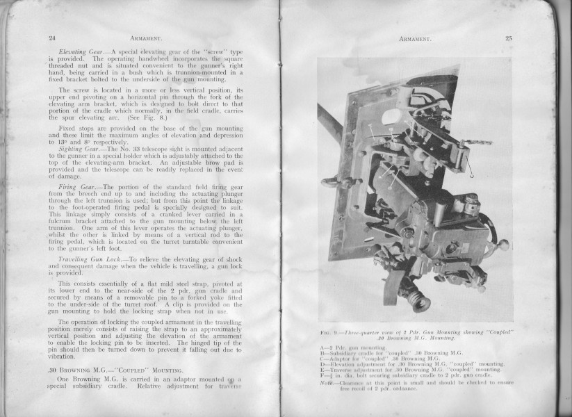
Another view with the co-axial Browning mount
There is a fundamental difference in the layout of the Car, in that the driver's position is slightly to the right and the gear and range-change is moved to the left.

Slightly different driver's position and controls
Because the engine and gearbox are mounted back-to-front, the 2-wheel-drive option is still to the front axle and the rear wheels are only engaged when 4-w-d is selected. A single range selector lever replaces the two for the Marmon Herrington transfer box.
The full lubrication diagram is also shown, giving an even better lay-out of the Car:

Lubrication diagram
Stuck on to the front cover is an advertisement for the M.O.S (Ministry of Supply?) Auction Sales, dated December 1950. Below the heading is a line reading 'Arranged for December, and up to 12th January 1951'. I couldn't have made it to the Auction, I was born at 4pm on the last day!

Auction notice stuck to the front cover
:-) Andy Selfe
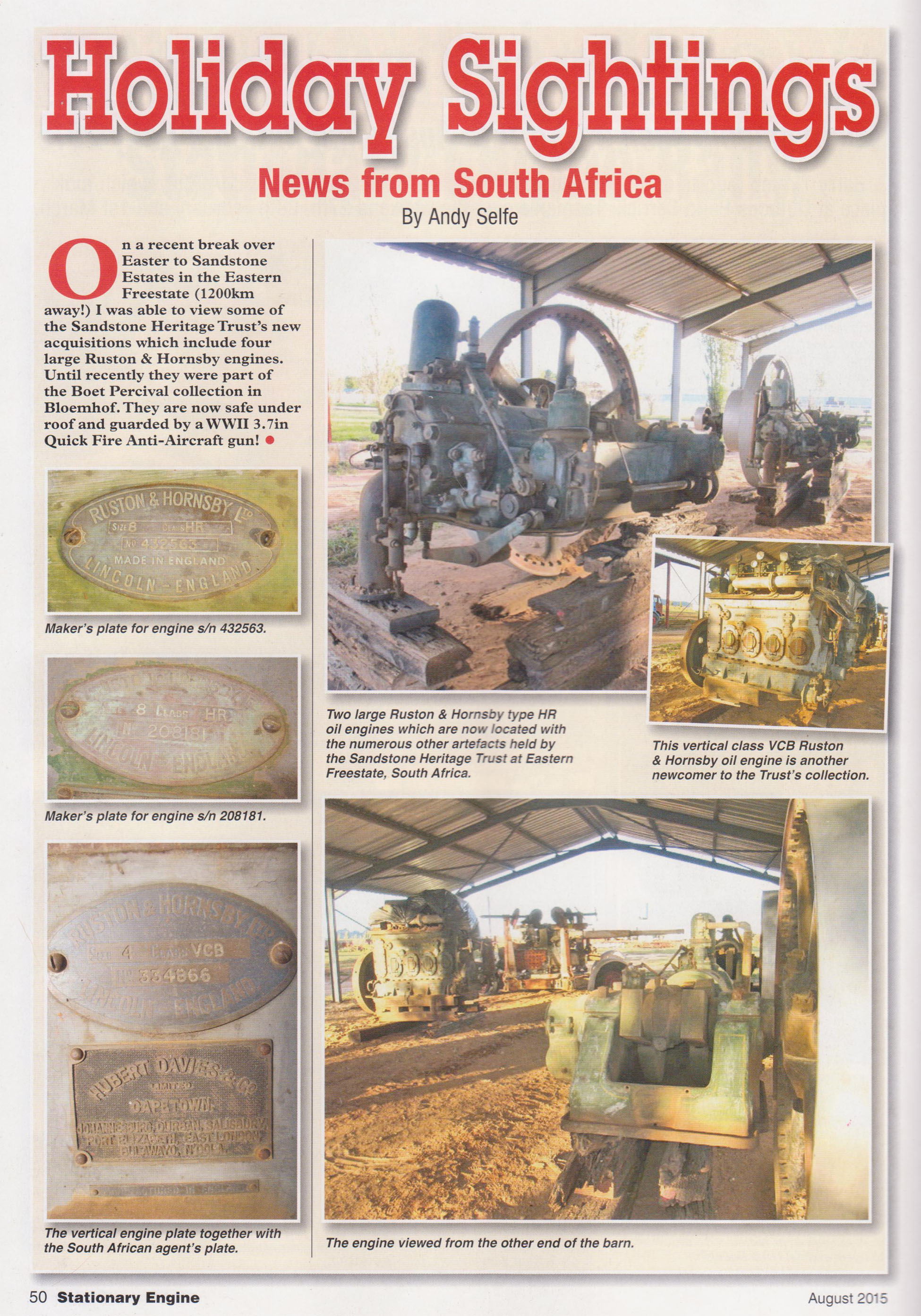
Spacer for Flywheel and Adaptor Plate for Perkins, Engine Rooms
26th July 2015
The white paint arrived on Thursday, same code on the tin, so the wrong paint was in the right tin last week! It's Plascon Synlac Enamel and it's as thick as treacle. I thin it down and paint several coats by hand. It dries very quickly so one can start in one corner of one of these Engine 'Rooms' and by the time you get back to the same place, it's dry for the next coat!

Engine Room all ready for the Ford
The Engine Room for the Ford is now ready to hang the engine and gearbox, and in this week, Johan Stemmet sent the Thames gearbox, flywheel and a clutch across from Robertson. The lining of the driven plate had become detached and was stuck on the pressure plate, so that needed chiselling off and we've sent the driven plate away for relining.

It's going to be fun working in that clean, white Engine Room!
The diff and shocks got a coat of black. It's going to be a pleasure working in there!

Diff and shocks are painted black, it looks good in the white Engine Room
I then started cleaning and priming the Engine Room of the other Car which will have the Perkins engine. The engine mountings will need very little modification, so I've left the whole frame in. I haven't decided yet whether to re-use the one fan and shaft assembly which came with the two Cars, or to use an electric fan like I've fitted to the Ford radiator.

Cleaning and priming the Engine Roome for the Perkins, bracket for the fan shaft on the left
This was cleaner than the other one and less rusty, so I got quite a lot done. I wonder whether some of the sand and earth in the deepest corners doesn't come from the Sahara Desert! Once again, what I've finished cleaning with the wire brush when I go off to do another job, I prime. In that way, bit by bit, it gets finished. I've been through some cup brushes and release oil so far!

We're on the third tin of release-oil and the fourth cup-brush!
Today was sunny and calm so I cleaned up some more panels on the outside of the Cars and primed them, also priming with the green Plascon UC501 primer over the res NS4. I noticed what looks like a burst of machine-gun fire was stopped by the side of one of the Cars, whether in anger or the dreaded target practice, we will probably not ever find out! There are six dents like this.

Bullet marks?
The steel disc for the spacer for the Perkins flywheel arrived this week and was machined flat and parallel and bored for the pilot bearing. There is an annular groove in the back to clear the heads of the flywheel itself. The spacer is fixed to the flywheel like the Hyster torque converter was, with three bolts from the engine side, tightened through the starter hole in the bell housing. Six holes were marked and drilled on the right pitch circle for the pressure plate.

25mm thick spacer for Perkins flywheel
This clutch and pressure plate comes straight off the remains of the V8 Ford engine.

Clutch and pressure plate from the original V8 loosely in place
There were still three holes in the adaptor plate to mark out, drill and tap. I used a 90 degree scriber through the holes in the gearbox bell-housing .

Marking out with a 90 degree scriber
Then removed the plate, centre punched and drilled and tapped the three remaining holes.

Tapping the last three holes on the Perkins adaptor plate
This is certainly the most straightforward adaptor plate I've ever made!

Adaptor plate for Perkins... straightforward!
There was evidence of oil having leaked out of the rear of the gearbox, so it was necessary to take off the output flange.

The castle nut was tight!
The old seal could then be levered out as a sample. the size is bound to be in inches! I cleaned the gasket faces on top of the gearbox and refitted the cover with gasket maker. The gearbox then got a coat of primer, that will be black, too.

Gearbox output flange off and seal removed
So once the seal is installed, the Perkins can be assembled, engine, flywheel, spacer, adaptor plate, clutch and gearbox, ready to hang....... once that Engine Room is painted! I have to have the original radiator checked and cleaned first, let's hope that doesn't need a re-core!
We still need two wheel rims. One of the widened rims has the dish in the wrong place, so I expect I'll have to drill out the rivets and move it. The width we have widened the first three wheels to is dead on 9".

235mm, 9" exactly!
However, I'm rather hoping that it might be possible to try the tyres on the non-widened rims! But I still need to break up the concrete in those tyres! I tried today with a sledge hammer, it's a good mix and well cured!
:-) Andy
Ford Radiator, V8 Clutch, Gearbox and Engine Mounting on Perkins Engine, Handles on the Nose-Cone, Wheels and Primer
19th July 2015
The radiator was finished on Friday, ready to install in the Car with the Ford engine, but I want to paint the engine spaces of both Cars white. I opened the 5 litre tin of Plascon Synlac to find it pitch black! The only white paint I could find was an ancient tin with about half a litre, so I painted what I could with that. I drilled the two rectangular spacer tubes three times each, primed and painted them and installed the assembly.
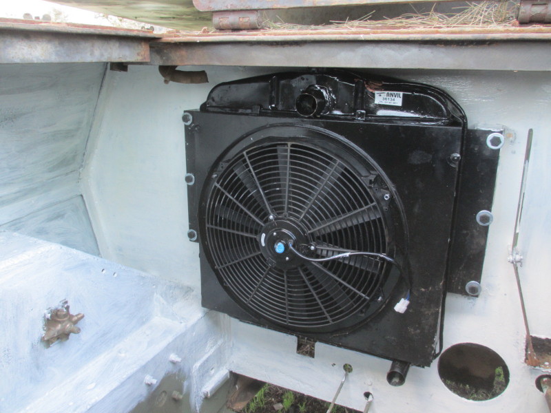
Radiator for the Ford engine fitted
In the process while I was in the turret to tighten the first nut, it fell down and the top tank scored a dent, but I doubt there's any long term damage. The filler neck corresponds nicely with the cover in the armour plating above. When I've finished painting the white, we'll be ready to hang the Ford engine and Thames gearbox and see how to make up the engine mountings.
While the paint was drying, I tackled the removal of the clutch from the Ford V8 engine. The pressure plate is bigger than the diameter of the bell housing and there is one notch in the bell housing where a socket can be used to tighten or loosen the fixing bolts. However, the engine is seized, so the flywheel couldn't be turned. I had to use a die-grinder to make six more notches just big enough to get a small socket in.

Two extra notches out of six for removing the clutch pressure plate
I didn't want to do anything drastic because the bell housing is part of the block and somebody, one day might desperately need one! Once all the bolts were out, the pressure plate still wouldn't come out! I checked with Johan Stemmet in Robertson but he only knows the truck versions. He did say, however thatit had to come out downwards. The lower part of the bell housing is part of the sump, so there was nothing for it but to remove all the bolts and drop it.

The sump had to come off to remove the pressure plate
Once out, I could inspect it. It looks like new, with brass woven into the lining material. Certainly suitable to re-use, just like it is!
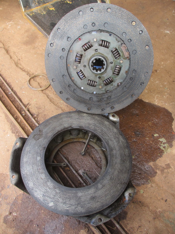
Clutch and pressure plate, like new!
This will be used with the Perkins engine combination. I am only waiting for the spacer plate to be machined and attached to the Perkins flywheel on that job, and at the same time the pitch circle can be marked out for the pressure plate bolts.
Because that combination is progressing so quickly, the next job was to drill and tap the holes for fixing the gearbox to the new adaptor plate. As I said before, it's important that the engine and gearbox both stand upright, so I used a set square across the top of the gearbox and lined it up with a flat vertical machined face on the bell housing and clamped it through the inspection cover on top.

Aligning the engine and gearbox
Using the holes to act as guides, I drilled centre marks with a 3/8" drill, then used a pilot drill followed by the tapping size for 3/8" (5/16"), tapped through the hole and fitted the first bolt, and so on, eventually removing the clamp to do the fifth hole.

Tapping the gearbox fixing bolt holes
There are still three out of the eight which will need marking out with a right-angle scriber because they are behind obstructions. But the gearbox is firmly in place!

Gearbox fitted! Still three holes to mark out, drill and tap
I was delighted to find, on opening one of the lockers, the missing bracket for the gear change! I was going to have to visit Ysterplaat Air Force Base Museum to remove theirs and trace it, this is no longer necessary! The next job was to free off the stuck gear selectors. The previously missing bracket with the slot can be seen in the picture below.
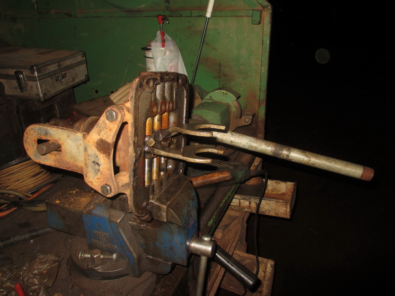
Freeing off the gear selector, with the slotted bracket in place
On a roll with the Perkins combination, I went on to drill the bracket I'd had flame-cut to replace the missing left hand engine mounting. I had removed the right hand one to trace for the new one, so I clamped the two firmly together and drilled the four holes, again using the full size drill to mark out, then a pilot hole before the ½" one to finish.

Drilling the new left hand engine mounting using the other as a guide
I didn't have bolts for it and there's some grinding to do to clear the step on the lower edge of the block. I could then measure from the gearbox mounting bolts to the front ones and work out how the combination might fit on the engine space.

Offering up the new left hand engine mounting
We have tracked down what we hope is the right colour for the Cars, RockGrip Desert Sand, and the tyres are expected any day. I want to deliver the rims painted before the tyres are fitted, so the next job was to wire-brush, sand and paint the three rims which have been widened. The dish of the middle rim has a different offset to the others. We will have to see if this matters.

First three wheels prepared and primed, waiting for the Desert Sand paint
We had such fine weather today so I decided to do as much preparing and priming as possible on the outside of both Cars. Pippa caught me on the job!

Caught on the job!
The Armour Plate has mostly withstood rust, but the thinner plate is rusty in places. This needed sanding and the application of anti-rust NS4. It looks so awful that I hurried to apply the normal Plascon UC501 primer!

NS4 primer on the rusted panels
There was another job to tackle on the dummy nose-cone; the lifting handles. I am making heavy duty handles out of 20mm round bar but I doubt they will be a perfect match, so I resolved to 'borrow' the engine cover lid handles from both Cars and make new ones for those, where they are less visible.

Engine cover lid handle 'borrowed'!
Next I had to make sure they were in the right place! Copying from the other one, using a straight-edge, I marked the position and angle.
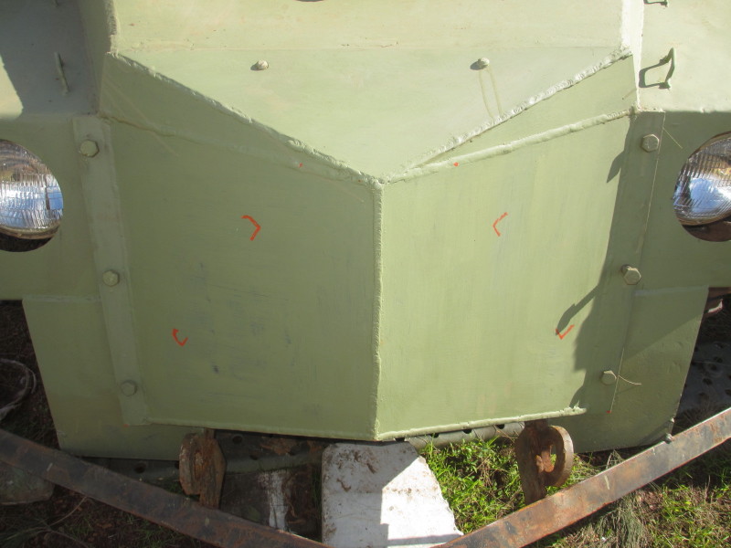
Dummy nose cone marked for handles
After tacking them in position, I took the nose cone off (again!) and welded them securely, primed and painted them.

Welding a handle to the dummy nose cone
The end result looks pretty authentic!

Dummy or the real one? A bullet will tell you!
By evening, quite a lot more was primed, on both Cars, either in NS4 or UC501.

Prepare, prime, panel by panel!
I was still hoping to wire-brush the gearbox for the Perkins, but the power went off! Load-shedding :-(

Perkins engine and Ford gearbox with adaptor plate
:-) Andy
Tyres, Paint, Adaptor Plate for Perkins, Radiator for Ford engine and Fuel Tank
17th July 2015
I realise now why I'm so excited to have found the 'Armour Rock' tread tyres. I found a picture of my own Eland when I was stationed at Runtu for the first three months of 1970. They are exactly the same! Five are on the way from Skidloaders in Petit.

This is also the colour we've been looking for, which I seem to remember being called Desert Sand. I did a web search and came up with the wrong colour. Adam from Ryke Hardware had better luck with a RockGrip colour chart, with not only the right colour, but the right name! It looks too light in this picture, but it's the green under the yellow showing through on the Car.

The steel ring for the adaptor plate for the Perkins engine arrived and I visited Orbit Engineering and found Vaatjie busy with it on the lathe. He was having problems with chatter at that diameter.

They lent me a big vernier to measure the two diameters, one on the engine and the other the newly ground outer diameter of the gearbox bell housing. The step on both sides is only 2mm deep, yet the plate fits snugly without any form of fixing! The recess for the gearbox can be seen on the outer face.

The next problem was to mark out and drill 11 unevenly-spaced holes for the fixing bolts. I asked Vaatjue to machine a concentric point on a short piece of 3/8" UNC thread and harden it. I couldn't work out how to screw it in and out; he thought of the screwdriver slot on the side!

I screwed it in all the way so just the very tip protruded from the flat face. I gave the plate a tap when the step was snugly in the register, took it off and I had a neat centre-punch mark! That I drilled a 3/8" clearance hole and attached the plate to the engine again with one bolt and the 'centre punch' in an opposite hole and tapped it again. I had to repeat the procedure ten more times, each time adding the latest bolt until all 11 holes were drilled. Each bolt screws in by hand now with the plate in the register!

The next job was to measure the depth of the flywheel from the gearbox face and to compare that with the measurement on the original V8 Ford petrol engine.

The difference is just on 25mm. See the calculations on my hand!

So the second part of the adaptor is to add a steel disc, 25mm thick to the back of the Perkins flywheel, bored for the pilot bearing, and to mark out, drill and tap six holes for the clutch off the Ford V8! There was more measuring to do: the pilot bearing must be 10mm below the clutch face. I can then offer up the gearbox into its register, make sure the engine and gearbox are both upright, then mark, drill and tap 12 holes in the new plate for the gearbox bolts!
The new core arrived for the radiator which was with the Ford engine in the forklift. I plan to fit an electric fan to this combination and found one on special offer, 400mm in diameter. I had a steel sheet cut to fix to the original radiator cowl.
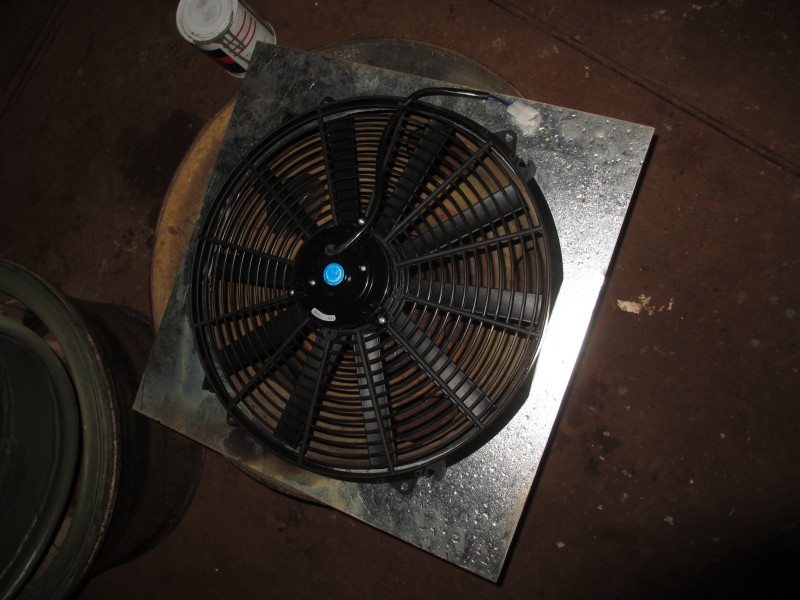
I had to drill four holes for fan mounting screws which Dennis from Anvil radiators soldered to the back of the sheet, because one can't get to them to hold them while tightening, before soldering the whole sheet to the original cowl. The result is neat!

Dennis didn't have good news on the fuel tank I removed last week, though. Even before cutting a hole in the side of the tank, he collected more than five litres of rust-flakes from inside the tank!

He did then cut a patch out of the side, but the whole tank is like a colander! So we'll have to re-think our plans there!
:-) Andy
Tyres, Engine Mounting, Scraping, Priming and Preparation for Ford Engine
12th July 2015
More good news is that, after a bit of time on the Internet, I tracked down tyres with the ideal tread pattern! We had thought we'd have to settle for Industrial Tractor-type tread which would have worked well, but not looked 'Military' enough. What I found were tyres with 'Armour Rock' pattern, as are popular on Unimogs. A set of five is on the way.

Armour Rock tyres, in 12.5/80 x 18
I was struggling to remove the engine mounting from the Car which will have the wider Ford engine. I want a completely clear engine space so I can hang the Ford engine and gearbox (the latter must still come from Robertson), have the propshaft lengthened and then I can make up a new cradle. By lifting one side of the old cradle too much, it jammed, so I knocked it back down, some shims fell out and I was able to lift the whole frame out.

Lifting out the engine and gearbox support bracket to leave an empty engine space
The fuel tank which was last used was a much-modified Land Rover tank on its side. There is already a neatly fitting fuel tank tucked away on the left hand side over the wheel-arch which will be more than big enough. It will need professional cleaning and testing, so I took both tanks out.

Old Land Rover tank on its side and fitted tank which I intend using, both removed
This leaves a completely empty engine space, which I set to and cleaned up with a wire cup-brush and sanding disc, prior to applying a coat or two of primer. I think a good proportion of De Brug training ground is now in my yard!

Empty engine space!
By Sunday evening, it was looking a lot better!

Engine space looking towards the back

Engine space looking forward
The radiator which came out of the forklift with the Ford engine fits nicely on the left, here I tried it out before I took the fuel tank out. I have two pieces of rectangular tube as spacers each side and the hole for the longer propshaft is clear. Although the core looked good, it has been found to be porous so it will be necessary for a new core to be fitted. The filler neck is in the right place for the inspection cover in the plate on top.

Testing the Ford radiator for fit
While I was busy with wire-brushing, I started at the front of the Car. The nose cone was off for priming anyway. I would not have liked to get down here if the front didn't come off!

Wire brushing down by the driver's feet
Soon, it was looking a lot better!

Primed as far as I could reach!
I am also wire brushing, sanding and priming other panels of the Car, one at a time. In fact, the other one as well!

Primer gradually taking over!
I'll be pleased when the tyres arrive; then I can put the rear wheels back on, chock them and safely lift the front axle and strip the brakes. As it is, I was able to strip out the brake pipes and hose to the back axle to have new ones made. No chances taken there!

Brake pipes and hose to the rear axel
At the same time, I took out the Brake Master Cylinder from under the front, to send for for overhaul.

Brake Master Cylinder viewed from underneath, before removal
It's a Lockheed type, popular on older Hyster and Clark forklifts I work on.

:-) Andy
Perkins Engine, Nose Cone, Wheels, Tyres and Engine Mountings
5th July 2015
There's lots to report on since last issue! The first piece of good news is that David Curry has kindly donated the red Perkins 4.203 engine to the project! Even better news is that it runs well, at least on Hennie the Engine Rebuilder's test cradle. David said it was overhauled several years ago and never ran, but he was worried about stuck valves from standing. The followers which pass through the cylinder head were indeed stuck in some cases, but Hennie's guys freed them off and with a starter I had from a MF 135 engine, it starts and runs nicely. It desperately needs hard work to do, to 'clear the cobwebs'!

Perkins 4.203 engine running in the test cradle
The rev-range of the engine is also acceptable, at 2860 RPM, I think there are settings for this engine at 3000 and beyond. I have read 63 BHP at 2600 RPM, maybe 70 at 3000?

The CAV DPA pump's plate, showing a maximum speed of 2860 RPM
I said before, making an adaptor plate for this engine will be extremely easy, now that the gearbox bell housing is completely round and concentric with the input shaft. The added advantage is that it will not be necessary to move the gearbox as this has a smaller bell housing than the Ford.
During the week, the first of the plates arrived for making a dummy nose-cone for the Car which had none. I measured from the other one, and had the first six plates cut. I marked and drilled, bolted and welded them together on the Car to start with, so I could cut a cardboard template for the two main plates. They are all 6mm Hot Rolled mild steel, nothing special, it must just look right.

First six plates of nose cone drilled, bolted and tacked, so a template could be cut for the two big pieces
The two big plates arrived on Friday and naturally I was keen to tack the whole thing together. It needed a bit of fettling to make the two plates join exactly in the middle with minimum gap.

Nose cone tacked ready for welding
This morning I took it off and welded it outside and inside. I had to weld a stiffener on to the back to prevent it from pulling during welding.

Inside of the nose cone welded, with stiffener to prevent pulling while welding
After fettling the outside to remove all the spatter, it was ready for primer.

Nose cone fettled, ready for primer
Hooked on the front of the Car, it would take an expert to tell it is a fake, I think!

Dummy Nose cone in place
More good news is that the first three wheels have been widened and are back here for priming and painting.

The first three wheels back from widening
We thought we'd have to settle for an industrial digger type almost tractor-type tread for the new tyres, but after googling, I seem to have tracked down a source of tyres with what I would call Unimog tread, but which is called Armour Rock in the trade. This is indeed excellent news!
This evening, I decided to carry on where I left off last Sunday night, getting the radiator out. It was loose, but to come out, it needs to be lifted out and the top armoured plating was in the way. Many of the bolts had been removed, but there were several countersunk screws with captive nuts which despite much soaking in release oil, refused to budge. I had to get inside and grind the captive nuts off the framework, and in so doing, cut through the screws.

Countersunk screws cut off under the framework to lift off the top engine cover
The top cover, along with the (heavy!) hinged lid could then be moved out of the way and the radiator lifted out.

Radiator ready to lift out
Last week I removed the four ¾" bolts between the chassis and the engine mounting assembly, the front section of which supports the gearbox and the radiator. With all those out, it should have been a simple job of lifting the framework out. Ha! The rear cross-member lifted out by hand, but the one at the front is resisting all efforts to pull it out, despite the whole Car's weight hanging from it, connected to a chain block!
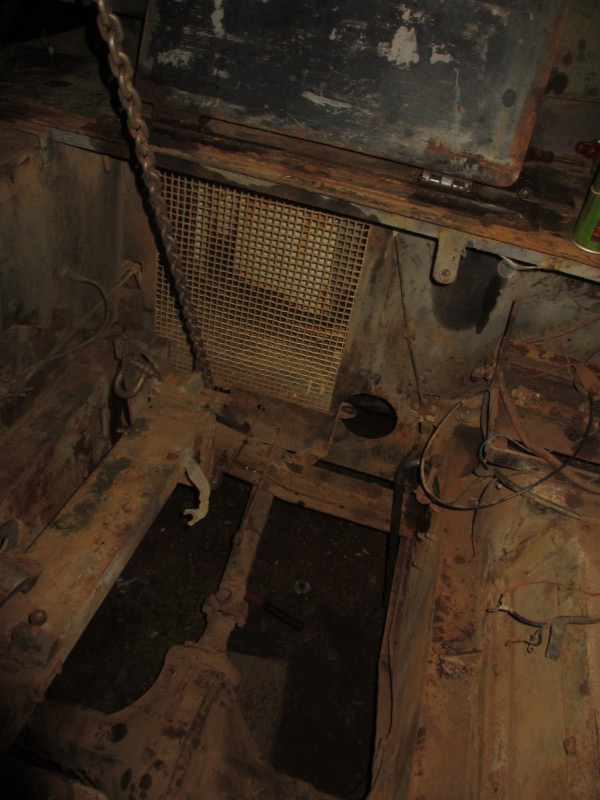
Trying to pull out the front part of the engine mounting frame with a chain block from the gantry
Somehow it will come out, leaving the entire engine space clear. The idea is to then hang the Ford engine in the space, along with a gearbox which has been promised along with the adaptor plate from Johan Stemmet in Robertson, then we can see what will be involved in fitting this engine and gearbox, which has to be closer to the centre of the Car, for the bell housing to clear the chassis.
Watch this space!
:-) Andy
Which Engine?
27th June 2015
Having now taken the vee-eight out and seen that there is no space to move the gearbox towards the centre of the vehicle, I have two options. One, if I am to use the Ford D series engine which has a large bell-housing, is to move the whole engine and gearbox further away from the transfer box, have a longer prop-shaft made, modify the gear shift link and re-make the engine and gearbox cross-members. All these mods are possible, but for just 25mm across, it's a lot of work!

The gearbox cannot be moved to the left, it is up against the radiator
The other possibility is to use a Perkins engine which I have found, it is available, is suitable for making and fitting a simple adaptor plate and the most important advantage is that the bell-housing diameter is such that the gearbox need not be moved across!

Perkins 4.203 engine out of a forklift
Its bell housing has a concentric register. Making an adaptor plate for an engine like this is easy. The flywheel, although not flat and ready to take a clutch plate, is at least solid and not a flex-plate as many are which come as this does, from a fork-lift.

The rear of the engine (on the right) with concentric bell-housing
The problem is on the gearbox. Although it looks as though the bell-housing is concentric on the outside, it isn't. It is a casting with a rough finish on the outer diameter and there is no inner register. Alignment between this gearbox and the original engine relied on two dowels only.

The bell-housing outside diameter looks concentric to he input shaft. It isn't!
So on the assumption that using the Perkins engine would be a simpler option, I made a tool to make the outside diameter concentric with the clutch release bearing sleeve. Gerhard at Orbit Engineering kindly turned a steel collar of the right inside diameter 'on the house' as a contribution to this project :-). He also lent me a bracket which they use to fix an angle-grinder into, which can then be clamped or welded to a tool. I chose the clamping option because I knew I would have to advance the setting after each 'cut'. I clamped it to a diagonal bar which I welded to the collar from Gerhard.

Simple tool, collar on the release bearing sleeve, diagonal bar and angle-grinder in a holder
The collar rested on the release bearing, making the whole assembly very easy to turn. Once I had done a 'cut', I stopped in a place where the disc wasn't touching, and gave the bracket a tap with a light hammer to bring the disc closer to the outside of the bell-housing and off I went again!
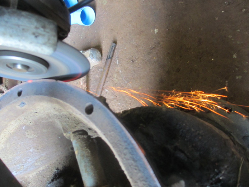
Grinding away gradually, a turn at a time!
I must have rotated the assembly about 100 times, or it felt like it! Eventually, the disc was engaged for at least 90% of the circumference, the areas where it didn't touch were spaced out around the outside, so there is enough surface to measure so that a step in the adaptor plate can be machined, into which the bell-housing can register. It is extremely important that the engine and gearbox shafts align exactly.

Ground outer surface of bell-housing to act as a register
During the week, I took two more wheels off and managed to remove the remains of the tyres with ease here on the farm, so there are three waiting for widening at Orbit. They will be widened outwards so that turning circle shouldn't be affected.
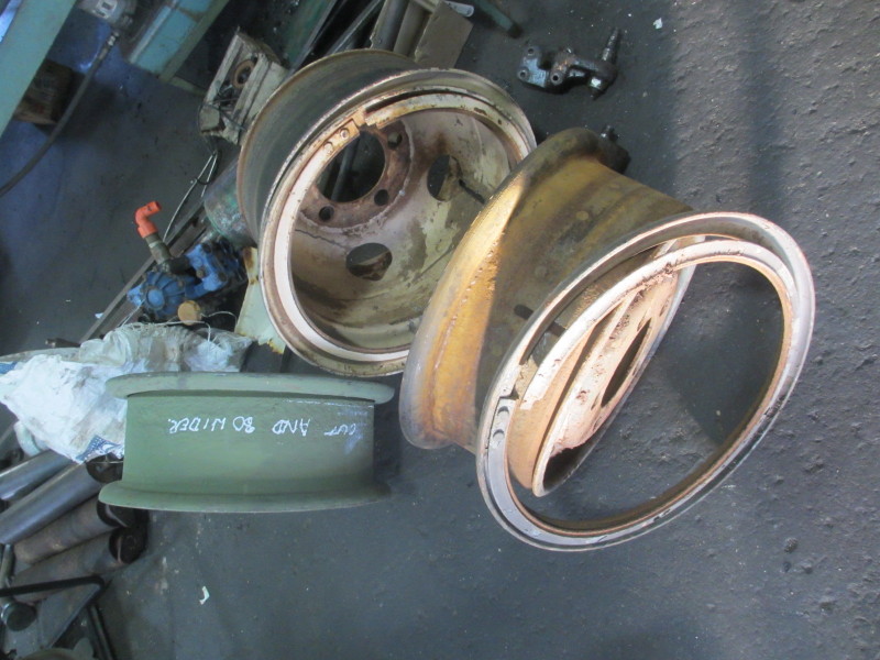
Three wheels waiting for widening
We had plenty of rain in the week. Enough to let the axle stands sink into the gravel of the (sloping) yard. We heard a noise one evening and this is what we found. I wondered first how the two cans of release oil spray were lying on the ground...... Oops! Glad I wasn't under it!

All fall down!
The rear end was easy to raise with two chain-blocks from the gantry, but the front is still on the ground. I want to get wheels back on at the back and block them before raising the front.
I had opened the brake drum on the front right hand side and all looks good. I will definitely have the slave cylinders overhauled and have new hoses and brake pipes made, but the drums and even the shoes look good!

The brakes look good!
Andy Selfe
Wheels, Tyres, Gantry and Vee-Eight-Out!
21st June 2015
After much discussion, we have decided to go firm on fitting 12.5/80R18 digger front tyres. They have the right diameter but they need to be fitted to a much wider rim. The new tyre at rest measures 230mm from bead to bead. The rim we have stripped measures 150mm, so the first rim, stripped and painted last week, is at the Engineering Shop to be widened by cutting the rim and welding in an 80mm wide flat bar, rolled to the correct 18" diameter.

The Armoured Car will look good on a set of these!
Apparently 18" 'flaps' are not available, so Saskias will cut and overlap a 20" one; they have done it before. These tyres are normally fitted to tubeless wheels and flaps are not necessary. I took so much trouble to save the flap from the old tyre, but it's too narrow!
I had been trying to work out how I would remove and refit engines, working on my own. A forklift isn't really delicate enough and you need a second person. I remembered I had a spare gantry at the workshop lying in pieces so I fetched it on Friday and erected it, on my own! Actually before he went home Kerneels helped me offload the beam from the roof of the mobile workshop on to the engine compartments of both Cars. It looked as if it would be long enough to straddle both Cars! I brought the A-frames home on the truck and offloaded the first at one end. The forklift isn't working so I had to use muscle power to lift the first end of the beam on to the top of the first A, then with a complicated system of chains and chain-block attached to the stationary forklift, raised the other end, complete with the traveller.

Pulling on the first A-frame with the legs chained to the Car
With little effort, the other end of the beam was up at the right height and I could reverse the lorry in and tip off the second A and juuuust get the second set of bolts in! I had to use the chain block to move the first A closer to the Car at that side to tighten all the bolts.
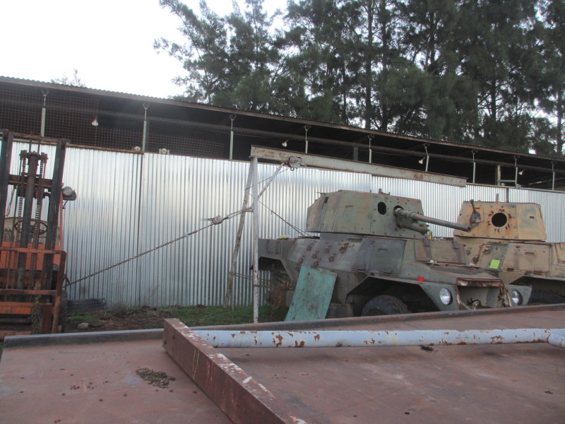
Using chain-block and chains to raise the other end of the gantry beam
So on Sunday morning, I used two chain blocks from the gantry and lifted the back of the Car without the wheel, moved it closer to the other and put it down on axle stands and blocks. Now the gantry is more than long enough to straddle both Cars!

The gantry now straddles both Cars with ease!
Then all was ready to remove the engine and gearbox from the second Car! Sounds easy? Not really! I had removed the gearbox from the other Car, but there's no radiator in it, everything is much more open. I couldn't get at the flange bolts on the prop-shaft to the transfer box, so I had to remove the U-bolts from the other pair of universal caps, then hammer them through towards the gearbox.

Nuts off the prop-shaft universal u-bolts, and it was still difficult to get the u-bolts out!
Next the two gearbox mounting bolts, which have split pins in. I didn't have kind words for the assembler who (how many years ago?) had forced the old split pins right in, so I couldn't grip the loops with a side cutter :-(. Split pins out, and it still wasn't easy to loosen off the castle nuts!

Using brute force to loosen the gearbox mounting nuts
Once the nuts were off on the other one, the bolts came out easily. This one was a different story! Much hammering with a 4-pounder, and nothing happened! There was another job while I was underneath, to disconnect the clutch linkage. I decided to try lifting the gearbox off the mountings, so I rigged two chain blocks from the traveller. Lifting the gearbox with one, the front of the engine lifted off its mountings (which had been removed in the past)!

Pulling with the chain block at the gearbox end, the front of the engine lifted!
With the pull from above, the two gearbox bolts eventually gave up the struggle and with more hammering from below, the engine and gearbox came away! I was able to operate the lever of one chain block with one hand, the chain of the other with my other, while guiding the engine out with both feet!

Guiding the engine with my feet while operating a chain block in each hand
Before long, it was out!

Engine and gearbox out!
A gentle push on the traveller, and it could be lowered into the gap between the two Cars.

Engine and gearbox hanging between the Cars. It was then easy to remove the prop-shaft flange
I could then remove the prop-shaft flange with ease and have a look inside the gearbox. This one had no top cover, and looking at 2nd gear (the smaller on the pair) one can see that the driver wasn't good at double-de-clutching! The other gearbox is in much better shape!

The gearbox had no top cover and 2nd gear has been badly treated
All that can be saved here is the clutch and pressure plate, maybe! I then removed the fan shaft and housing.

Fan and shaft assembly removed
While I was loosening the gearbox mounting, I made a critical observation. The gearbox is right up against the radiator. There is no opportunity of moving the gearbox towards the centre of the vehicle unless the radiator is modified.
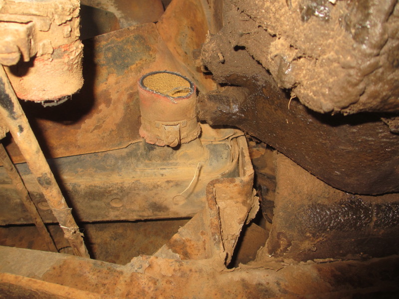
The gearbox is right against the radiator!
Looking into the now empty engine space, I think the best plan will be to remove the radiator and both front and rear engine mounting cross-members and to simply hang the diesel engine and gearbox in place and see if the whole assembly can be moved forward and the prop-shaft made longer. Both cross-members are made to bolt loose.

Engine and gearbox removed! The gearshift link can be seen protruding through the fire-wall. That will be another head-ache!
But first, the whole engine compartment must be cleaned, primed and painted!
I scratched around in the shed today and found some Convoy Lights I removed from a FFR (Fitted For Radio) Land Rover I used to own. They will look good on this Car!

Convoy Lights
Youth Day Progress
16th June 2015
It's been raining hard at times today but I did manage to get two jobs out of the way. One was the troublesome right rear tyre which wouldn't come off the rim. The Tyre Shop had tried all kinds of tricks, including soaking between the tyre and rim with Coca-Cola! They didn't want to do anything drastic, because they want to re-use the 'flap' which keeps the tube from being pinched between the beads of the tyre and the rim. I felt sorry for them and collected it on Monday and at the workshop, first cut the entire tread away from both side-walls. It was a dreadful job which I did with an angle grinder and a diamond-impregnated steel disc cutter. They had burned out a grinder trying with an abrasive disc!

Cutting both side-walls so whole tread could be removed and 'flap' saved
That left the remains of the side-walls and the flap. I first used a wire cup-brush to clean up all the rust on the exposed section of the rim and chipped away at the rust at the bead itself, then hit from inside outwards on the side-wall. I was wasting my time!

Outer side-wall stuck on the rim
I then used the wire cup brush again and wore-away the rubber in one area against the rim, until I came across what I feared, the steel wires! Now I know why you can tow a tractor with a tyre between chains to take up the shock. This was a Kelly tyre and K.T.A.T! I used a wood chisel to lever a few wires away from the bunch and cut them with a side-cutter one by one! Once cut, I folded them back and dug for more.
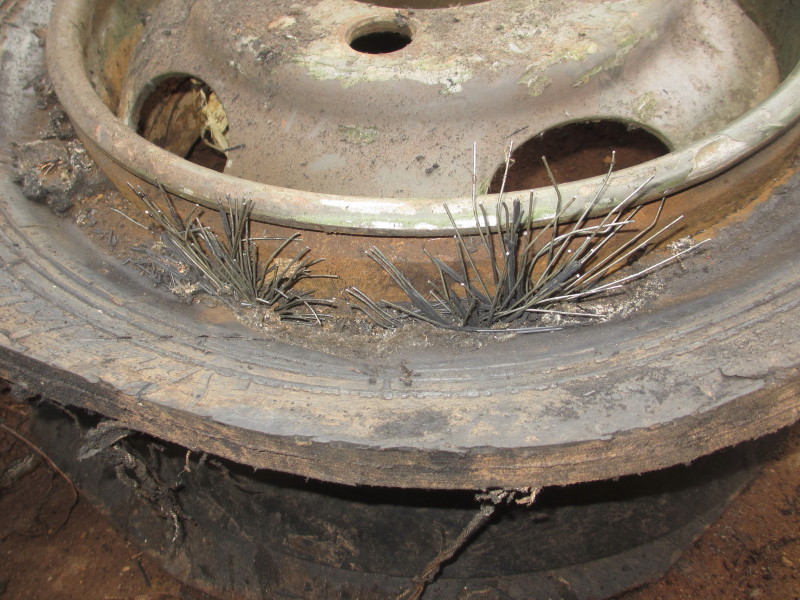
All those wires, and this was just the outside set!
When I couldn't find any more wires, I dug deeper with the chisel and then very deep, found more :-( At this stage, I folded the flap back to expose the inside of the side-wall and attacked with a grinder and a thin cutting disc and cut a section out and again levered wires out a few at a time and cut them one by one!

Levering steel strands out a few at a time to cut one by one!
Patience paid off and eventually I cut right through and had the outer side-wall off. I could then pull off the flap, intact!

First side-wall off, phew!
It was obvious what the problem was, thick flakes of rust which this side-wall had stuck on when the locking ring was removed. I chipped this all off with a welder's hammer and managed to remove the second side-wall without too much persuasion.

Both side-walls off and flap intact!
More wire-brushing was needed before a few coats of primer.

Rim all cleaned and primed!
We still haven't sourced the correct tyres, 10 X 18s. We might have to re-centre 8.25 X 20 rims and use tyres of that size, which are relatively easy to obtain and have the right diameter, or widen these rims to take 12.5/80R18s.
The other job was removing the gearbox I plan to use. The other has no top cover.

Gearbox prior to removal
At the same time, I'm investigating what it will entail to move the whole gearbox about 25mm towards the centre of the Car. I disconnected the short propahaft to the transfer box and was pleased to find it has a sliding spline, so no problems with the slightly longer distance. The mounting under the rear of the gearbox is fixed to the channel by 6 bolts, but I was removing these when rain stopped play!

Gearbox mounting bracket from underneath
I'm very hopeful that it won't be much of a problem to drill new holes that short distance away so that the bell-housing of the Ford D-series engine can clear the chassis. I managed to open the top cover of the gearbox and all looks very healthy inside!

Inside of the gearbox, all looks good!
An oil change, free-off of the selector mechanism, and I must make a bracket which is missing. I hope to borrow the one off the Car at Ysterplaat for critical dimensions!

Bracket on the Car at Ysterplaat Airforce Base, missing here
:-) A
Restoration Begins
13th June 2015
There has been time to inspect both vehicles and to make an assessment. The brief is to restore one to running condition, taking what is necessary off the other, and that the second be a 'static exhibit'. It is quite clear that what I'll call for the meantime, the 'green' Car, registration no U 52923 (from the plate at the driver's left shoulder) is in better condition. It is more complete, particularly in the turret, including a fairly complete 2-pounder Quick Fire Anti-Tank gun.

'Green' Car U 52923 and 'Yellow' Car U 53233
Having trained as a Gunner in the SA Armoured Corps, then on the French 90mm DEFA Gun and 7.62 Browning Machine Gun, I find this subject fascinating. Four bolts on a bracket have been removed and a rod bent. Also bolts have been removed from the elevating gear, so I'm doing a bit of stripping to rectify this. Threads are BSF on the Gun itself, not easy to source replacement bolts!
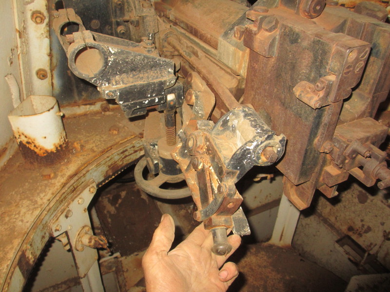
Bent rod on 2-pounder QF Anti-Tank Gun
Also the traversing wheel was missing, so I had to take the one of the 'yellow' Car. Again, one has to be careful with bolts, those on the Car itself are UNF and UNC!

Traversing wheel and gearing
For access to the bolts on the elevating gear, the Gun will have to be lifted out of its cradle, which means that the co-axial Browning bracket had to come off too.

Right-hand side of breech and co-axial Browning mount on the right
Having decided to focus on the 'green' Car, and because it will be standing outside, security is important. All the covers and doors are closed on both Cars, but only the green one had top doors, and those very scruffy, made of scrap pieces of chequer plate.
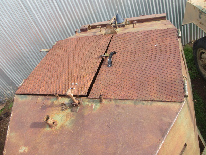
Scruffy top doors on the 'green' Car
I had two 4-mm steel plates cut and 'cross-bent', that is lightly kinked diagonally from corner to corner. This improves the stiffness of any steel sheet enormously. The hinges are good, so I cut the old doors off the hinges and put these doors, chequer-face down, on to the 'yellow' car. For the moment they are lying there loose; I have hinges for this job.

Scruffy doors, upside-down, loosely fitted on the 'yellow' Car
The new doors fitted very nicely between the old hinges, just a bit of trimming was needed at the middle when the plates had been welded to the old hinges. I then added an overlap at the middle on the Crew Commander's side and two spring-loaded barrel bolts.

Steel strip welded to the Crew-Commander's side door for an overlap
The other side now has a handle and an all-important hasp-and-staple and a padlock! It was dark when I finished.

New top doors fitted to the 'green' Car
The green paint is Plascon UC501 primer; I plan to paint this Car 'Desert Sand' when I get that far.
:-) A